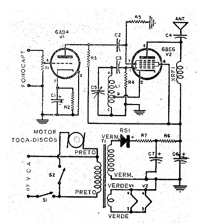
This circuit transmits the signal from a crystal pickup to a midrange radio at a distance of up to 100 meters. The antenna is a piece of ordinary wire 2 to 3 meters long.
The circuit uses two tubes and as in all circuits of this type, in addition to the valves, the critical component is the transformer. This transformer, however, can be altered by one of the possible sources that we described in the article Sources for Tubes.
The tubes are the 6AB4 which consists of a preamplifier and the 6BE6 that functions as an oscillator, modulator. Coil L1 consists of an oscillating coil for valve 6BE6 or can be wound with 20 + 70 turns of 28 AWG wire in a 1 cm diameter tube.
The variable capacitor can be a padder or tapped from a medium-wave tube radio.
The other components of the circuit are:
R1 - 1 M ohms - potentiometer
R2 - 270 ohms x 1 W
R3 - 100 k ohms x ½ W
R4 - 22k ohms x 1/8 W
R5 - 10 M ohms x 1/8 W
R6 - 1k5 x ½ W
R7 - 27 ohms x 1 W
C1 - 10 uF x 25 V - electrolytic
C2 - 4.7 nF - ceramic
C3-47 pF - ceramic
C4 - 100 pF - ceramic
C5 - padder or variable
C6 - 40 uF x 150 V - electrolytic
C7 -22 uF x 150 - electrolytic
XRF1 - 250 uH
RS1 - 1N4007
T1 - 125 V X 15 mA and 6.3 V X 600 mA
In figure 1 the complete diagram of the apparatus.


