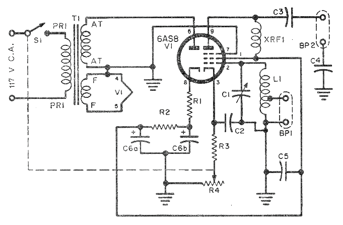
From a 1958 publication, we find this interesting circuit of an antenna preamp for the 21 MHz (15 meter) band, but changes can be made in the coils for operation in other bands, up to the limit of the valve, around 50 MHz.
In addition to the dual tube, the other critical component is the transformer having secondary 125 V x 25 mA. However, given the low current and also voltage, a simple self-transformer can be used, as in the article Sources for Tubes that we give on this site.
The L1 coil consists of 8 turns of 26 coreless wire with a diameter of 2 cm. XRF1 is a 2.5 mH shock. The other components:
R1 - 3k3 x 1W
R2 - 1k x 1W
R3 - 220 ohm x ½ W
R4 - 3k (3k3) x ½ W
C1 - Tube circuit variable - 140 pF
C2, C4, C5-10 nF - ceramics
C3-1 nF- ceramic
C6a, C6b-22 uF x150 V - electrolytes
In figure 1 the diagram of the pre-selector.


