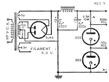
This interesting stabilized power supply circuit of 300 V and 150 V (regulated) was obtained from a technical documentation of 1958. The critical components, as always are the tubes and the transformer, in addition to the filter shock.
The circuit shown utilizes gas regulating tubes which are the time equivalents of the valves of the zener diodes. Each valve regulates the voltage at 150 V.
The current is low, in the range of a few hundred milliamps and the filter shock can be done with a transformer of 110 V x 6 V x 300 mA taking advantage of its primary winding.
Note the voltage of the filter capacitors and that the single resistor should be wire with 10 W dissipation.
In figure 1 the complete circuit of the source.


