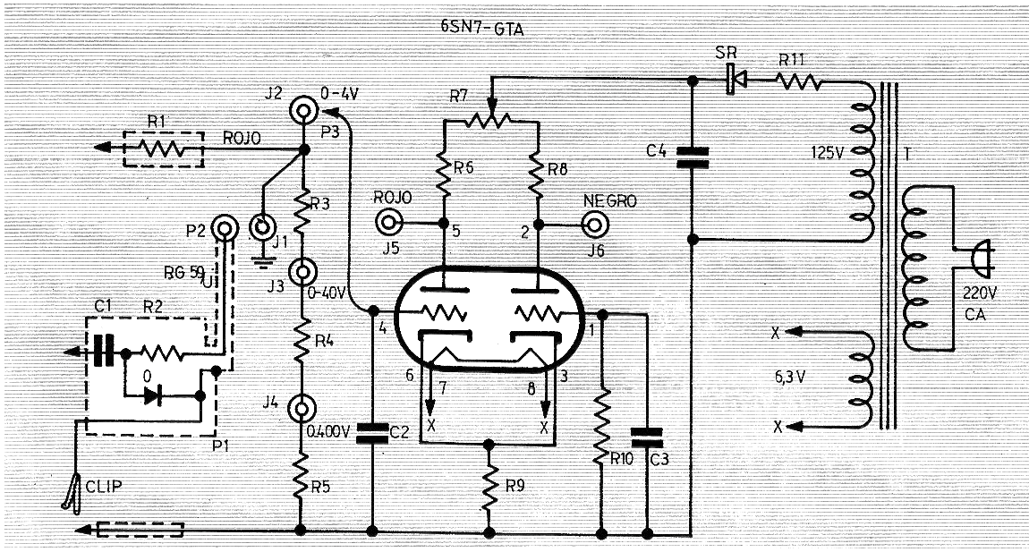
With this circuit it is possible to use a low-cost analog multimeter with a low sensitivity of 1000 ohm per volt at 20 000 ohm per volt with high-impedance valve multi-meter (VAV) with high sensitivity.
We found this project in a 1969 publication and the critical elements are the double tube and the transformer.
The design simply consists of a DC amplification stage with high input impedance and low output impedance using a 6SN7 valve.
The circuit has scales of 0 to 4 V, 0 to 40 V and 0 to 400 V, being still quite current in relation to the performance.
The components not indicated in the diagram have the following values:
R1 - 1 M ohm
R2 - 3.3 M ohm
R3 - 9.1 M ohm
R4 - 0.91 M ohm
R5 - 0.1 M ohm
R6, R8 - 10k ohm x 10W
R7 - 4k7 Potentiometer
R9 - 600 ohm
R10 - 10 M ohm
R11 - 100 ohm x 5 W
C1 - 470 pF - ceramic
C2, C3-10 nF at 47 nF - ceramic
C4-10-10 UF-200V Electrolytic
D1 - 1N4004
T1 - 125 V x 15 mA + 6.3 V x 600 mA
We remind you that R3, R4 and R5 must be precision resistors and resistors with power not indicated are ½ W.
Figure 1 shows the complete diagram of the adapter.


