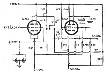
Operational amplifiers are not modern circuits. What we show below is a tube version of an operational amplifier from a 1965 technical document.
In this circuit, the input differential pair is formed by the double triode 12AX7, which in the modern equivalent consists of two married transistors.
The signal from this step is taken to a class B output with a double tube 6EA8 which provides a low impedance signal. The electrical properties of this circuit are the same as a common operational amplifier.
The power comes from an external 300 V supply and there is a voltage reference circuit that normally consists of a divider connected to one of the inputs of the operating. In this circuit it consists of an external source whose voltage is adjusted by a potentiometer.
In figure 1 we have the complete diagram of this amplifier.


