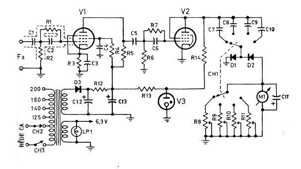
The circuit shown in this article was obtained from a technical documentation of 1965. It uses as an indicator a milliammeter of 0-100 uA and has 4 scales that allow measuring frequencies up to 100 kHz.
The accuracy will depend on the settings. In addition to the transformer, the critical components are the tubes. The rectifier diode in addition to D1 can be the 1N4004 and D2, D3 are 1N34.
The transformer has 200 V secondary with 60 mA. The components used are:
V1 - EF94
V2 -EL84
V3 - OA2 or VR150
R1 - 100 k ohm
R2 - 250 k ohm
R3 - 2k2 ohm x 1 W
R4 - 1 M ohm x 1W
R5 - 100 k ohm x1 W
R6 - 1 M ohm
R7 - 250 k ohm
R8, R9, R10, R11-1 k ohm - trimpots
R12 - 500 ohm x 5 W
R13 - 2k2 ohm x 5W
R14 - 2k x 4 W
C1, C3, C5, C7 -100 nF x 600 V
C2-10 pF x 600 V
C4-47 nF x 600 V
C6 - 500 pF x 600 V
C8 -10nF x 600 V
C10 - 100 pF x 600 V
C12, C3 -50 uF x 350 V
LP1 - 6 V x 250 mA
M1 - 0-100 uA
Figure 1 shows the complete diagram of the frequency meter.


