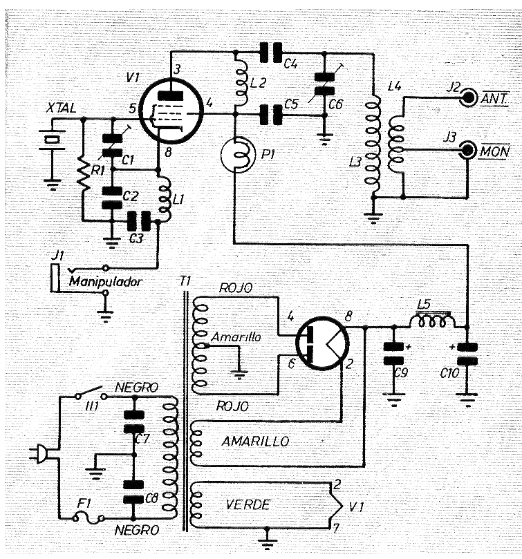
Here is a traditional transmitter for the bands of 3.5 and 7 MHz radio amateurs, indicated at the time for beginners who wanted to assemble their first equipment. Despite the power, with a good antenna it was possible to make transmissions at distances of hundreds of kilometers or even thousands of kilometers.
The project was obtained from a foreign publication of the 1960s and is based on the 6V6GT tube.
In addition to the tubes the transformer is the other critical component, whereas the coils are of homemade construction, details of which are given in figure 2.
The transformer must have secondary 480 V (240 + 240 V) with 40 mA plus winding of 5 V x 2 A and 6.3 V x 1 A.
The components used in this transmitter are:
V1 - 6V6GT
V2 - 5U4G
C1 -trimmer 7-35 pF
C2 - 100 pF x 500 V - ceramic
C3-22 nF x 500 V - ceramic
C4-47 nF x 1600 V - ceramic
C5, C7, C8 - 4.7 nF x 500 V - ceramic
C6 - variable
C9, C10 - 20 + 20 uF x 450 V - electrolytic
F1-1 A
R1 - 82k x 1/8 W
P1 - 28 V x 40 mA
L1, L2 - 2.5 mH
L3, L4 - see figure 2
L5 - 8.5 H - small power transformer primary
Figure 1 shows the transmitter diagram.


