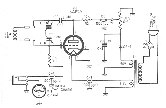
We find the diagram of an RF oscillator in a publication of the 1960s. The circuit uses a 6AF4A and the frequency generated depends on the coil L1. Coils for ranges from 1.5 MHz to 300 MHz can be used.
The transformer in the original is for the 220 V x 50 Hz mains, but a 60 Hz unit can be used for the 110 V or 220 V mains. The diode can be 1N4007 and the operating point adjustment is done in R3.
The operating indication is made by a milliammeter that measures the tube grid current when the oscillation occurs.
The capacitors are ceramic except C3 which is an electrolytic for 250 V. The variable can be obtained from a radio valves. The coils are made with wire 28 in 2.5 cm diameter PVC or cardboard tubes. The number of turns between 2 and 60 depends on the frequency range generated.
In figure 1 the complete diagram of the oscillator.


