

We found in a 1967 documentation the circuit of a small domestic transmitter station spanning a few tens of meters, using three tubes. Once the tubes are found the assembly is relatively simple since the only transformer the circuit uses is a small output transformer which can even be replaced by a 110 V x 6 V transformer with current of 250 mA or close to that , no problem. The antenna coil powder is formed 80 + 40 turns of wire 28 in a 2 cm diameter tube. The variable capacitor is of the type commonly found in medium-wave radios. The antenna is a piece of wire stranded from 1 to 3 feet in length. Note that this circuit must be enclosed in an insulated box because it is not isolated from the power supply and may cause a shock.
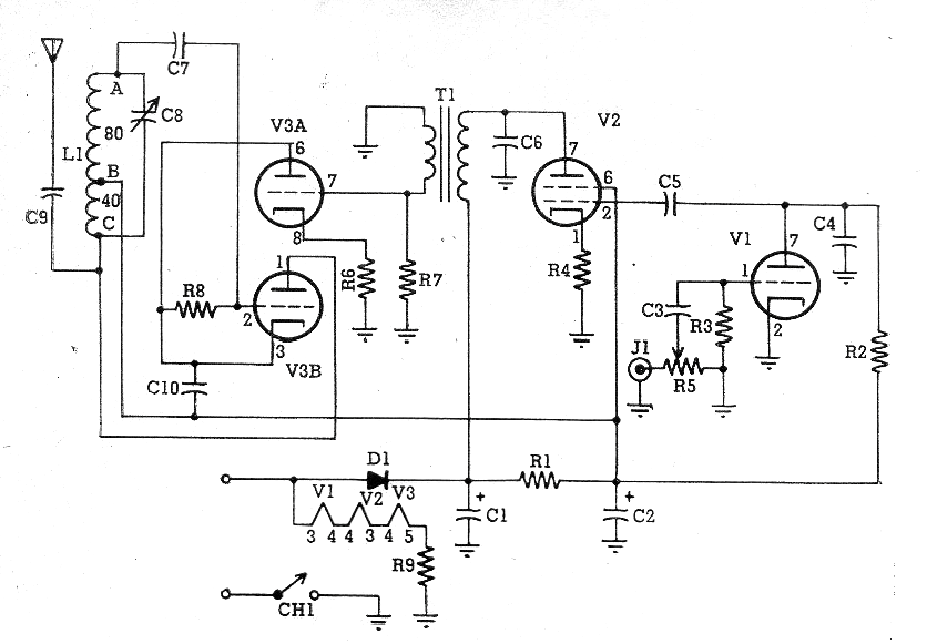
Material:
V1 - 12AV6
V2 - 50C5
V3 - 12AU7
C1, C2-22 uF x 250 V
C3, C5, C6 - 4.7 nF - ceramics
C4, C7, C10-470 pF-ceramics
C8 - Variable - see text
C9 - 100 pF - ceramic
R1 - 2k2 x 1W
R2 220 k x 1 W
R3 - 10 M - ½ W
R4 - 150 ohm x 1 W
R5 - 470k - potentiometer
R6 - 2.7 k x ½ W
R7 = 470 k1; 2 W
R8 - 22k x ½ W
R9 - 150 to 220 ohm x 10 W - wire
D1 - 1N4004 or equivalent


