
The valve circuit that we present was obtained from a 1970 documentation. The power supply is not included, it can be used from the amplifier itself or other equipment with which it works. The purpose of the circuit is to improve the dynamic range of an audio signal by increasing the strength of the weak signals and decreasing the strength of the stronger signals so that the range of intensities is narrower.
The circuit is based on 3 valves and is connected to the output of a preamplifier or other signal source. The luminous signal of a valve is optically coupled to an LDR (R9) so as to control the strength of the audio signal. The material used is given in the list below.
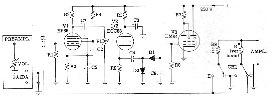
V1 - EF86
V2 - ECC83
V3 - EM84
R1 - 1 M x 1/2 W
R2 - 18k x ½ W
R3 - 220k x 1w
R4 - 1 M x 1 W
R5 - 68k x ½ W
R6 - 100k x ½ W
R7 - 470 k x ½ W
R8 - 2.2 M x ½ W
R9 - Photo-resistor LDR
R - resistor according to the sensitivity of the amplifier
C1-10 nF
C2, C4-330 nF
C3 - 8 uF x 400 V - electrolytic
C5 - 25 uF x 25 V - electrolytic
C6-270 nF
P1 - 1 M - linear
D1, D2 - BAX17 or equivalent - silicon diode