This means that in the open field or on a liquid surface, in case of boat control, we will have the greatest scope. It also greatly influences the size of both the receiving antenna and transmitters that can be between 1.2 and 1.8 meters for best results.
The transmitter can be powered by medium or large batteries or even with a rechargeable battery. The voltage will be between 6 and 12 Volts, with 12 Volts we will get the longest reach.
The assembly of the device is relatively simple since we only have one tuned circuit and its adjustment as well.
THE CIRCUIT
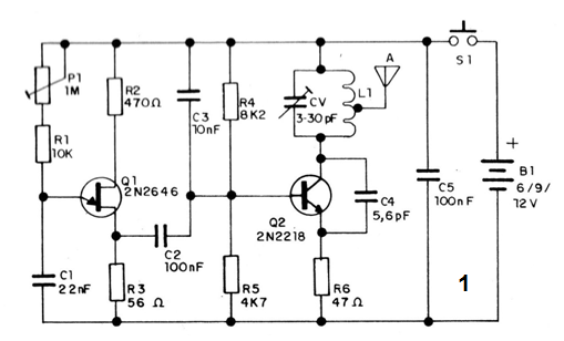
The high frequency step uses a power transistor that generates signals that are applied to the antenna. In this oscillator, the coil L1 together with CV determines the operating frequency. In this circuit, as in the previous ones we used a coil of 4 turns that produces a signal in the FM band, thus facilitating its tuning even by common receivers.
The feedback comes from C4 which can actually have values ??between 4.7 to 10 pF, but must be ceramic and of good quality.
The modulation is obtained from a relaxation oscillator with a unijunction transistor. In this circuit, C1 is charged via trimpot and R1 until the transistor trips by discharging the capacitor. With the discharge the transistor turns off and a new charge cycle is produced. P1 determines therefore the rate of loading and discharge and the frequency of the oscillations.
The audio signal is taken from the base 1 of the unijunction adjacent to R3 and applied via C2 the high frequency step modulating the transmitter.
The purpose of P1 is to obtain a tone that provides a good performance in the triggering of the receiver.
ASSEMBLY
The transmitter diagram is given in figure 1.

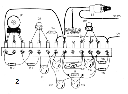
As it is a circuit that is not very critical, we can realize its assembly even based on a bridge of terminals as shown in figure 2.

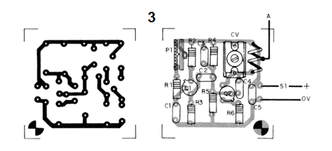
Of course, for a better array of components we can use a printed circuit board as shown in figure 3.

The coil L1 is formed by 4 turns of wire 22 or thicker in a non-cored form 1 cm in diameter. CV is not critical and porcelain or even plastic types can be used.
The transistor Q1 must be of the unijunction type 2N2646, not being equivalent. For Q2 we can use the original 2N2218 or else try more common types like the BD135 or the 2N1711.
The resistors can have dissipations from 1/8 watt and two capacitors must all be ceramic type disk
PROOF AND UTILIZATION
We can use any of the receivers from the previous projects or even an FM radio. By activating the transmitter by pressing S1 and adjusting CV, we must capture an audio tone at a free point in the range. This tone must be set to P1.
The range will depend on the supply voltage, the antenna used that can be telescopic or a hard wire and the sensitivity and good adjustment of the receiver.
SEMICONDUCTORS
Q1 - 2N2646-unijunction transistor
Q2 - 2N2218 or equivalent - RF transistor
RESISTORS
P1-1M (trimpot)
R1 - 10 k ohm (brown, black, orange)
R2 - 470 ohm (yellow, violet, brown)
R3 - 56 ohm (green, blue, black)
R4 - 8k2 ohm (gray, red, red)
R5 - 4k7 ohm (yellow, violet, red)
R6 - 47 ohm - resistor (yellow, violet, black)
CAPACITORS
CV-3 - 30 pF (trimmer)
C1 - 22 nF (ceramic)
C2 and C6-100 nF (ceramic)
C3-10 nF (ceramic)
C4-5.6 pF (ceramic)
VARIOUS
L1 - coil - see text
S1 - Pressure switch
B1 - 6 to 12 V - batteries or battery
Printed circuit board or terminal bridge, mounting box, battery or battery holder, uncles, telescopic antenna, solder, etc.


