The circuit is powered with a voltage of 12 V that can come from battery or source with a capacity of at least 1 amp.
The circuit is modulated in tone and has two amplifying stages of RE, which means that two frequency adjustments must be made in the apparatus, thus requiring a little more skill from the assembler than in previous versions.
The receivers can be the ones of the previous versions according to the type of operation you want and for better performance your antennas must be at least 80 cm in length.
HOW IT WORKS
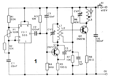
An integrated circuit of type 555 functions as an audio oscillator, thus providing the modulation signal to the transmitter. The frequency of the audio oscillator is basically determined by C1 and set to P1.
Depending on the application C1 can be changed.
The audio signal modulates an oscillating step based on a 2N2218 transistor. In this step, L1 together with CV1 determines the operating frequency. In the basic design they specify this coil to operate in the FM range, but changes can be made in order to operate in the lower range of VHF, which guarantees greater immunity to interference from local stations in the receiver.
The signal generated by this step, already modulated in tone, is applied to a power amplifier stage with another 2N2218 transistor. The signal is coupled via L2, while R6 and R7 polarize the base of the transistor.
In the collector of the transistor we have another circuit tuned formed by CV2 and L3. This circuit must be adjusted so as to ensure maximum signal transfer to the antenna.
R7 should eventually be changed in the range of 1 k to t0 k in order to ensure a lower resting current for the output stage and thus a better circuit performance that will approximate a class C operation.
ASSEMBLY
In figure 1 we have the complete diagram of this transmitter of remote control of greater power.

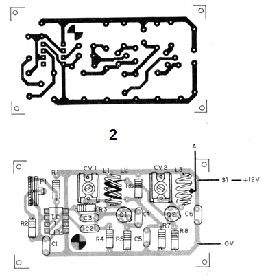
In Figure 2 we have the arrangement of its components on a printed circuit board.

L1 and formed by 4 turns of yarn 22 in a 1 cm mold without a core, L2 is formed by 3 turns of the same yarn and woven in L1. The coil L3 is formed by 5 turns of wire 22 in a 1 cm mold with central socket for the connection of the antenna.
The integrated circuit must be mounted on 8-pin DlL bracket. The resistors are all 1/4 watt with 5% or more except R8 which is 1 watt. The transistor Q2 must be equipped with a small heat radiator, since it tends to warm when in operation. All capacitors are ceramic type disk. The trimmers can be 2-2opF or 3-30 pF. This circuit will operate in the FM range being therefore compatible with all receiver designs we have seen so far.
ADJUSTMENTS AND USE
The test of operation is made simply by connecting in close proximity an FM receiver or a remote control receiver that has a handset or amplifier output.
We set CV1 to the desired operating frequency on a free channel and CV2 for maximum output signal intensity using a field strength meter.
In P1 we set the tone of the modulation signal, choosing one that allows greater efficiency in the activation of the relay or other load of the receiver.
The antenna must be telescopic at least 1 m in length and the operation must be done vertically. In open field and well adjusted this transmitter must have very high range, depending on the sensitivity of the receiver.
SEMICONDUCTORS
Q1 and Q2 - 2N2218 - RF power transistor
Cl-1 - 555 - integrated circuit
RESISTORS
P1 - 100k (trimpot)
R1 - 22k ohm (red, red, orange)
R2, R3 and R7 - 10 k ohm (brown, black, orange)
R4 - 6k8 ohm (blue, gray, red)
R5 - 100 ohm (brown, black, brown)
R6 - 47k ohm (yellow, violet, orange)
R8 - 22 ohm 1 W (red, red, black)
CAPACITORS
CV1 and CV2 - 3-30 pF - trimmers - see text
C2 and C6 -100 nF (ceramic)
C3-10 nF (ceramic)
C4 - 4.7 pF (ceramic)
C5-1nF (ceramic)
VARIOUS
L1, L2 and L3 - Coils, see text
A - antenna - see text
Printed circuit board, mounting box, socket for the integrated, uncles, solder, etc.


