Weak signals in the VHF range cause problems with images with drizzle and other problems in analog TV.
In the FM band we have problems of distortions and even signs that oscillate, disappearing at certain moments.
If you have these problems, we describe a small amplifier that you interlace between the antenna and the receiver and that can help a lot.
Of course the circuit will work in cases where the signal reaches an antenna, not solving the problem if we have no signal to amplify.
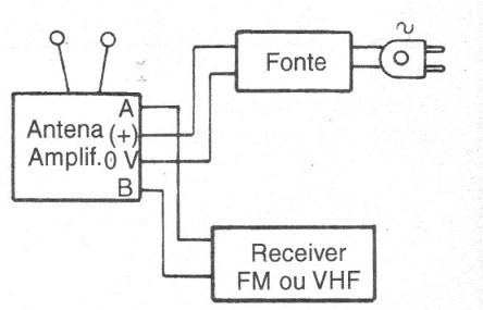
Ideally, the circuit should be positioned next to the antenna, with the long power lead going to where the source is.
The circuit has a good gain in the frequency range of 50 to 150 MHz.
Assembly
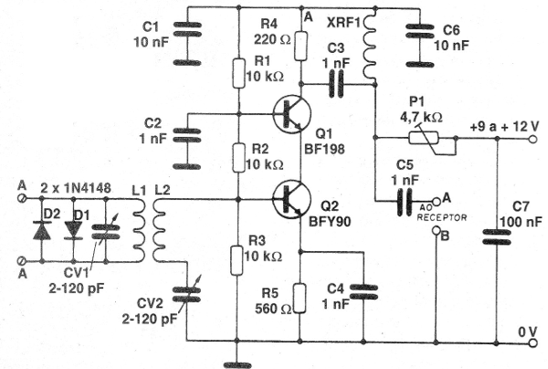
In figure 1 we have the complete diagram of the antenna amplifier.

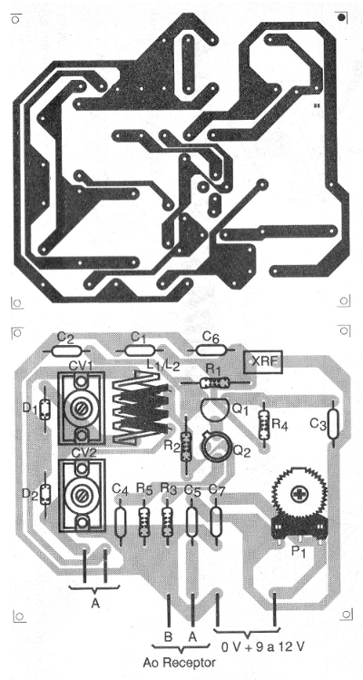
In figure 2 we have a suggestion of printed circuit board for its assembly.

On assembly, observe the position of the transistors and the polarity of the diodes.
The capacitors should all be ceramic and the resistors 1/8 W with any tolerance.
The coil L2 consists of 3 turns of rigid telephone wire with a 1 cm diameter without a core.
L1 consists of two turns of the same wire connected in L2 as shown in the figure in which we have the printed circuit board.
XRF1 is a shock of 1 uH or can be "fabricated" by winding about 5 turns of wire 32 or close on a toothpick.
The trimmers can be of more modern types from 2-20 to 4-40 pF round plastic, and modifications of the design of the board to accept this type of component should be made if used.
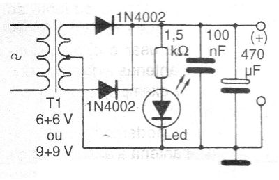
In Figure 3 we have a power supply for the circuit, although it can also be powered by a small 9 V battery.

The consumption is very low, and any transformer with secondary can be used from 50 mA.
The LED indicator that the power is on is optional.
In figure 4 we have the way of connecting the circuit between the antenna and the receiver.

To use, simply tune to the desired station and adjust trimmers and trimpot for better reception.
Q1 - BF198 or equivalent - RF NPN transistor
Q2 - BFY90 - RF NPN Transistor
D1, D2 - 1N4148 - silicon diodes of general use
R1, R2, R3 - 10 k ohm - resistors - brown, black, orange
R4 - 220 ohm - resistor - red, red, brown
P1 - 4k7 ohm - trimpot
C1, C6-10 nF - ceramic capacitors
C1, C3, C4, C5-1 nF - ceramic capacitors
C7 - 100 nF - ceramic capacitor
CV - trimmers - see text
XRF - 1 uH - shock - see text
L1, L2 - Coils - see text
Other Materials:
Printed circuit board, mounting box, power supply or battery, wires, solder, etc.


