The French mathematician Fourier has shown that any signal, independently of its waveform, can be decomposed into a sinusoidal signal of the same frequency and an infinite quantity of sinusoidal signals of multiple frequencies, which is harmonics, as shown in Figure 1.
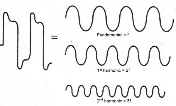
It was only with the development of electronics that the importance of this fact became a patent, with its wide use in electronics, telecommunications, DSPs, from the synthesis of sounds to computers.
In fact, if an FM transmitter produces a signal at the 100 MHz frequency, and is not perfectly sinusoidal, i.e. a pure oscillation, it will also radiate weaker signals in the frequencies of 200, 300, 400 MHz, etc.
The intensities are dropping, so that for the highest harmonic oscillations, the possibilities of causing interference are low, as suggested in Figure 2.
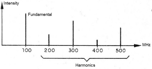
It is for this reason that citizen-level transmitters operating at around 27 MHz interfere with the low-channel analog TVs operating at around 54 MHz.
This frequency corresponds exactly to that of channel 2.
Many readers who try to adjust their small FM transmitters may inadvertently generate harmonics which will fall into the higher channels of the VHF TV range.
Notwithstanding the interference they cause, these undesirable oscillations "steal" the power of the transmitter, since it must be distributed between signals of different frequencies.
In other cases, there may still be oscillations called "spurious" which will fall on the TV and even FM band, in addition to those in which we wish to transmit, causing serious problems for those trying to adjust a transmitter: more than one signal is picked up along of the band and we do not know which one to consider.
By adjusting the transmitter at undue points, the power and the range drop.
Even with powerful transmitters it will not be possible to go beyond a few hundred meters under these conditions.
This problem is more pronounced in transmitters which have several tuned stages of amplification, as shown in Figure 3.
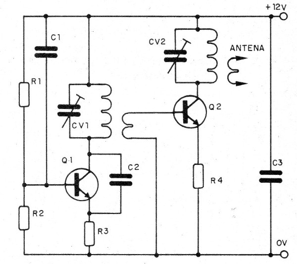
Small differences in the settings of two coils, inverted polarization of transistors that deform the signal and help in producing harmonics are some problems which can occur.
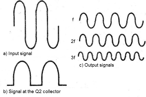
It is very common that, in order to obtain a higher efficiency of a transistor in a stage of amplification of signals, it is polarized in class C, as shown in Figure 4.
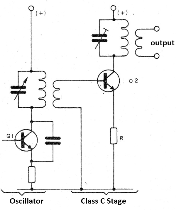
Under these conditions, it remains un-driven (in the cut) until one of the half-cycles of the signal reaches at least 0.6 V and polarizes the base-emitter junction to conduct.
The result of the operation in this configuration is a strong deformation of the signal, responsible for the production of a large quantity of harmonics which steal power and cause many interferences, as suggested in Figure 5.
Of course, in addition to the existing prohibitions which prevent the operation of such devices, except in a depopulated or with very low power places, we can have problems of the most diverse nature.
Solutions
It is not enough to build the transmitter and simply connect to an antenna any way, even if it is a simple piece of wire, to have a pure signal and a greater range.
The antenna coupling is an important first point to consider.
With a good adjustable coupling, we can transfer to the antenna the greater signal power at the desired frequency, reducing the amount of harmonics and obtaining greater reach.
In Figure 6, we have a suggestion of antenna coupling circuit which helps make a better transfer of the signals.
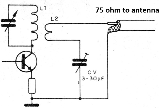
For the FM range, the coil is formed by 3 turns of wire 22 wound on the coil of the last amplifier stage of the transmitter.
The trimmer is 3 - 30 pF being the old type of porcelain or modern plastic.
The circuit must be adjusted for maximum antenna power.
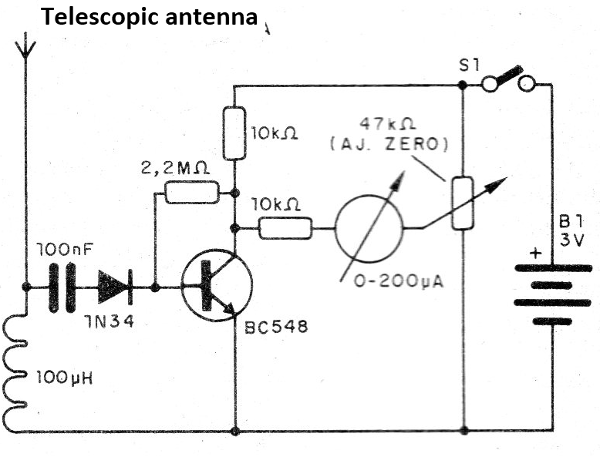
A field strength meter, such as Figure 7, should be used for this purpose.
For the AM range, where the problems are smaller, the coil is formed by 12 to 15 turns of wire 28 on the coil of the last stage of the transmitter and CV is a variable of 120 pF.
The frequency range covered by this circuit ranges from 500 kHz to 2 MHz.
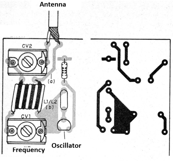
Note that this circuit must be installed in a metal box which works as a shield.
In Figure 8, we have a printed circuit board for the assembly.
Another problem which may occur in the outputs of the transmitters is that being the low impedance circuit, the Q factor is low.
With this, we have a low selectivity and the passage of signals that do not correspond to the frequency that we want to transmit.
This problem can be solved by using filters.
For the FM range, for example, we have the filter shown in Figure 9, which consists of a low pass type T filter.
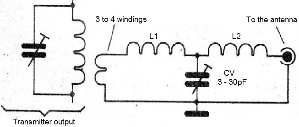
It has low signal resistance, tuned to the frequency we want to transmit, blocking the harmonic signals.
L1 and L2 consist of 4 or 5 turns of wire 20 or 22 in the shape of 1 cm without a core.
Another important type of filter is the PI configuration (of the Greek letter) and has its configuration shown in Figure 10.
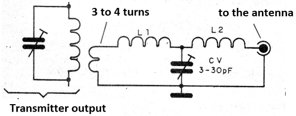
In this circuit, we can have the tuning of the trimmer and the coil.
We find this circuit in valve transmitters with output configurations like the one shown in Figure 11.
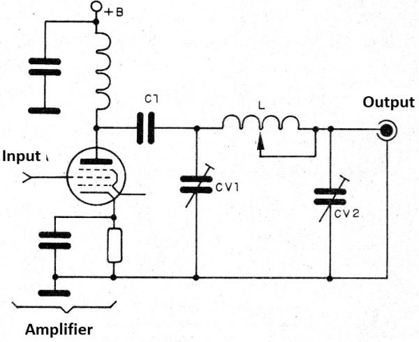
For the FM range, the coil L1 is formed by 5 twists of wire 20 or 22 in the shape of 1 cm in diameter without core and we can have a socket by turns for adjustments.
The trimmer is 3-30 pF with a good insulation voltage in the case of the tubed circuits.
The same circuit may be modified to a PI-L configuration as shown in Figure 12.
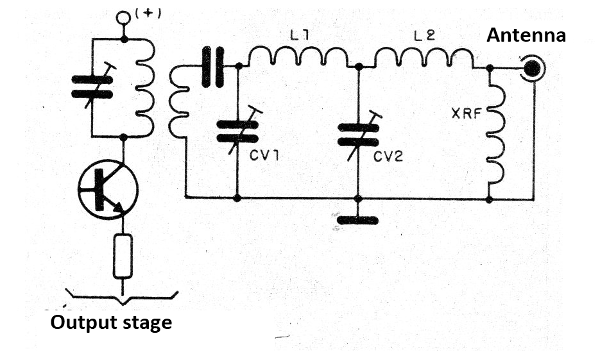
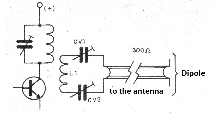
Many attach their transmitters to dipole antennas, using parallel lines (300 ohms), in which case the circuit of Figure 13 may be used.
Other coupling options for balanced lines are shown in Figure 14.
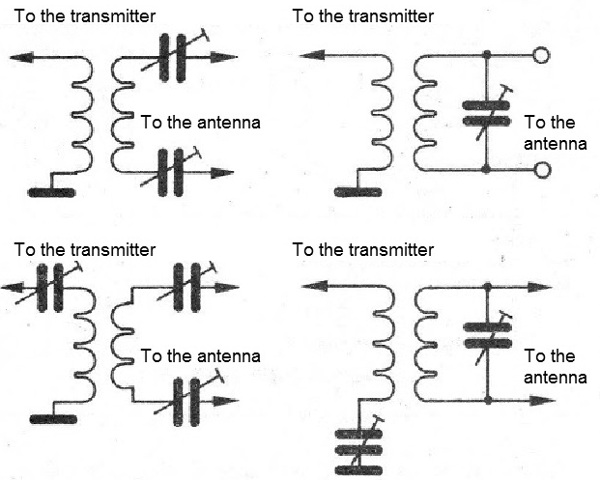
For the FM range, coil L2 has 6 to 7 turns of wire 22 or 24 on L1.
Conclusion
As we have seen in this article, one of the important points to achieve a good performance of a transmitter is in the coupling between stages and between the transmitter and the antenna.
The use of filters is also important to avoid the irradiation of undesirable signals.


