Features
Power supply voltage: 3 to 6 Vdc
Frequency range: 88 to 108 MHz (or VHF)
Range: 150 to 300 ft
Number of transistors: 1
This transmitter uses a PNP (positive-negative-positive) transistor instead of an NPN (negative-positive-negative) type, which is the basis of most of these projects. Despite this, the circuit has excellent performance as a substitute for those that use ,NPN transistors.
The charge carriers in an N semiconductor material can flow at higher speeds than in a P semiconductor. As a result, NPN transistors can operate at higher frequencies than equivalent PNP transistors.
The NPN transistor has only one P layer to be traversed by the charge carriers, whereas the PNP has two layers. Despite this fact, we can find many PNP transistors that are suitable for use in high-frequency oscillators, reaching frequencies as high as those used in FM transmissions.
In the circuit, we include a PNP Japanese transistor 2SA1177 (or any equivalent) to form a small FM transmitter that resembles the one in Project ART003E.
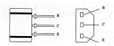
The recommended transistor has a terminal layout as shown in Fig. 1 and can produce signals at frequencies up to 150 MHz.

Using this transistor, we create a small FM transmitter that can send its signals to receivers placed at distances as great as 300 ft, depending on the power supply voltage, the antenna, and the local topographic conditions (presence of hills, obstacles, etc.).
Our project is very interesting from a didactic point of view, as the reader can compare its performance with that of the transmitter shown in Project ART003E
The principal characteristics found in the recommended transistor are:
Vceo (max): 20 V
Vebo(max): 30 V
Vebo (max): 5 V
Ic (max) 30 mA
PC (max): 150 mW
fT = 150 MHz (min); 230 MHz (typical)
hFE (according suffix) D: from 60 to 120 - E from 100 to 200 - F from 160 to 230
These characteristics are provided as a reference for the reader who needs to find an equivalent transistor that is suitable for this application.
How It Works
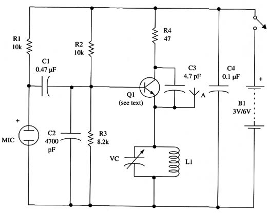
The transmitter is formed by a simple one-transistor oscillator that produces the high-frequency signal. The frequency is determined by L1 and CV and can be adjusted to any free point in the FM range between 88 and 108 MHz.
CV is a common trimmer rated 2 to 20 pF, but this component is not critical, and any trimmer with its highest capacitances in the range between 20 and 50 pF can be used.
The feedback that keeps the circuit in oscillation is given by C3. Depending on the operational frequency, this capacitor can be replaced with others to achieve better performance. Values between 2.2 and 5.6 pF can be used experimentally.
Resistor R4 limits the current flow through the transistor and therefore the power. Values below 47
2 must not be used, as the current flow through the transistor can rise to high values, heating this component to a dangerous point.If the circuit is powered from a 9 V supply, the signals can reach up to 800 ft, but the value of resistor R4 must be increased to limit the current flow through the transistor to secure values. So, this resistor must be altered to 82 or 100 ohm.Base biasing is made by resistors R2 and R3, and at the same time C2 decouples this electrode. As this part of the circuit operates with high-frequency signals, all of the capacitors must be ceramic types.The modulation comes from an electret microphone. Because this kind of microphone has an internal field effect transistor (FET) that is used to increase the signal amplitude (acting as an amplifier), the sensitivity is very good. Of course, the reader can use other microphones such as ceramic or crystal high-impedance types simply by removing R1.The signals coming from the microphone are applied to the transistor by C1.This capacitor value must be altered if the reader wants to change the audio frequency response that passes through it. Large capacitors will reinforce the bass, and small capacitors will give a good boost to the treble.The antenna is a piece of solid wire, plastic covered or not, 45 to 150 ft long, such as the one used in Project ART003E. The same general recommendations about its connection are valid here. Assembly The complete schematic diagram of the transmitter is shown in Fig. 1. 
The components are placed on a printed circuit board as shown in Fig. 1. 
Depending on the power supply (2 or 4 AA cells), the reader can choose an appropriate size plastic box to install all the components. If using AAA cells, it is possible to make the transmitter small enough to be easily transported in your pocket.The coil consists of 4 turns of AWG 18 to 22 enameled wire with a 1 cm dia. (air core) as in the project ART003E.All the capacitors are ceramic types except C1, which could be a plastic film unit or equivalent. Adjustment and Use of the Transmitter The device is adjusted and used as described for Project in ART003E.
Semiconductor
Q1 - 2SA117 7 PNP RF transistor or equivalent, Sanyo (see text)
Resistors (1/8 W, 5%)
R1, R2 - 10,000 ohm - brown, black, orange
R3 - 8,200 ohm - gray, red, red
R4 - 47 ohm -yellow, Violet, black
Capacitors
C1 - 0.47 µF ceramic or plastic film
C2 - 0.047 µF ceramic
C3 - 2.2 to 4.7 pF ceramic
C4 - 0.1 µF ceramic
CV trimmer (see text)
Additional Parts and Materials:
MIC - electret microphone (two terminals)
S1 - SPST toggle, or slide miniature switch
B1 – 3 to 6 V,2 or 4AA cells
L1 - coil (see text)
Printed circuit board, battery holder, plastic box, antenna, wires, solder, etc.


