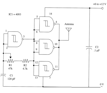
With a small antenna connected to the transmitter, you can receive the signals at distances up to 3 ft (1 m). Thus, you don’t need to use wires or physical connections on the receivers you’re calibrating.
Frequency adjustment is made by R1 in the AM range (LF and MF). A Morse key can be connected between the circuit and power supply to create a CW transmitter.
A complete schematic diagram of the transmitter is shown in Fig. 1.

The antenna is a length of wire of between 1 and 6 ft.
To use the device, place an AM receiver tuned to an unoccupied point of the spectrum, near the transmitter. Adjust R1 in the transmitter While pressing the Morse key until you detect the signal.
IC1 - 4093 CMOS integrated circuit
R1 - 47,000 ohm - potentiometer
R2 - 4,700 ohm, 1/4 W, 5% resistor
C1 - 120 pF ceramic capacitor
C2 - 0.1 µF ceramic or metal film capacitor


