Obs. This article was published in a Brazilian magazine and translated into English to be part of one of my books.
Features
Power supply voltage: 6 Vdc
Range: 3 to 4 ft
Frequency range: audio (400 Hz to 5 kHz)
System used: magnetic loop
An important application for this device is in science fairs or as a project in technology education involving telecommunications. But the basic application suggested for this project can also be used to communicate with a friend in an adjacent room.
The circuit is a magnetic loop transmitter/receiver operating with signals sent by the magnetic field and produced by a coil. The circuit is intended for very short-range communications. Its principal advantage is that the signals can pass through solid objects such as walls.
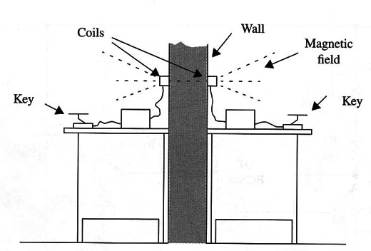
The power supply comes from four AA cells, and each unit can both receive and transmit signals. Using a pair of these devices, the reader can achieve two-way communications. Figure 1 shows how the circuit can be used as a room-to-room intercom.

How It Works
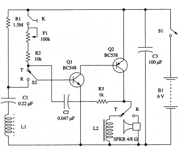
The circuit is formed by a two-stage transistor amplifier that can be used both as an amplifier and as a low-frequency oscillator, depending on the position of S1.
When S1 is in the receiver position, the signals picked up by L1 are applied to the base of the first transistor and amplified. The amplified signals appear in the second transistor’s emitter from which they are applied to a small loudspeaker.
When S1 is in the transmitter position, the circuit acts as an audio oscillator where the frequency is determined by C2 and the adjustment of P1. The audio signal is applied to a coil (L2), producing the magnetic field.
Note that, for best performance, the magnetic field lines produced by the transmitter’s coil should intercept the receiver’s coil as shown in Fig. 2.

The current drain is higher when the device is transmitting. In the receiving state, the current drain is determined by R1. The reader must conduct experiments to find the best value for this component. Values between 470 k ohm and 2.2 M ohm can be tested.
Assembly
Figure 3 shows the complete diagram of one unit, including a receiver and a transmitter circuit.

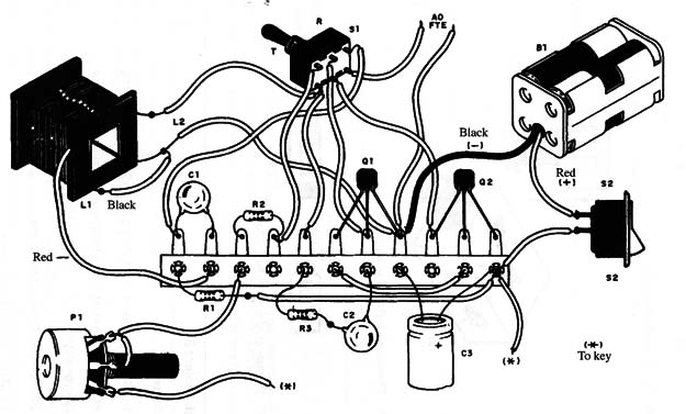
As the circuit is experimental and intended for beginners, the components can be mounted on a terminal strip as shown in Fig. 4.

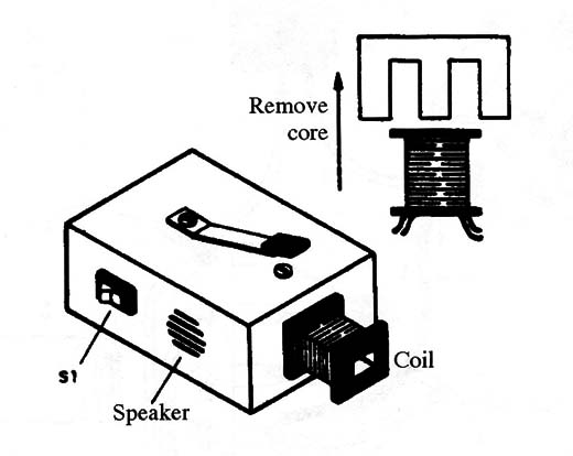
The coils are a power transformer’s windings. The metal core is removed, and only the windings are used.
For the receiving unit (Ll), the primary 117 Vac winding of any small power transformer can be used. The low voltage winding (6 to 12 V X 150 to 500 mA) can be used.
Any small 4 to 8 ohm loudspeaker or earphone can be used to reproduce the signals. The dimensions of the plastic box will be determined largely by the loudspeaker’s dimensions.
The Morse key can be a homemade version built with a wooden base and metal plates as shown in Fig. 5.

P1 can be a common potentiometer adjusted to determine the transmitted tone or, if the reader prefers, a trimmer potentiometer. Figure 6 shows the device installed in a plastic box and ready to be used.

Testing and Using the Circuit
To test the circuit, you will need to build two units of this circuit, with one placed to receive the signals and the other to transmit them as suggested in Fig. 7.

After powering up the units, press the Morse key in the transmitter. The signals should be reproduced in the receiver’s loudspeaker or earphone.
If the circuit cannot send signals more than a few inches, indicating low sensitivity, alter the value of R1 and also reduce the value of C2. Placing a small ferrite core inside the coils will increase performance. Try this solution.
Semiconductors
Q1 - BC548 or equivalent general-purpose NPN silicon transistor
Q1 - BC558 or equivalent general-purpose PN P silicon transistor
Resistors (1/8W, 5%)
R1 - 1,500,000 ohm - brown, green, green
R2 - 10,000 ohm - brown, black, orange
R3 - 1,000 ohm -brown, black, red
P1 - 100,000 or 220,000 ohm – potentiometer
Capacitors
C1 - 0.1 µF ceramic or metal film
C2 - 0.022 µF ceramic or metal film
C3 - 100 µF/ 12 WVDC electrolytic
Additional Parts and Materials
S1 - DPDT toggle or slide switch
S2 - SPST toggle or slide switch
B1 - 6 V, four AA cells
L1, L2 - coils (see text)
SPKR - 4 or 8 ohm - small loudspeaker (2 in.)
M1 - Morse key
Terminal strip, plastic box, battery holder, Wires, solder, etc.


