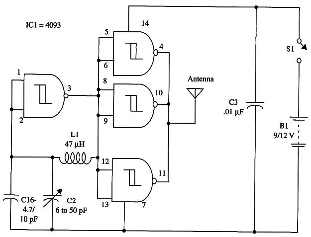
The circuit drains only a few milliamperes from the power supply, which can be formed using a 9 V battery or 6 AA cells.
As in the CMOS oscillators, the upper frequency limit depends on the power supply voltage, in this application a minimum of 9 V is required for a 3 to 4 MHz operation. With a 6 V supply, the frequency upper limit will fall to 2 MHz.
Experimental applications employ a single antenna wire 1 to 6 feet long, but you can also connect an appropriate external antenna to operate in the 80-meter ham band.
A complete schematic diagram of the transmitter is shown in Fig. 1.

1C1 - 4093 CMOS integrated circuit
L1 - 47 µH RF - choke (see text)
C1 - 4.7 or 10 pF ceramic capacitor
C2 - 6 to 50 pF trimmer, Radio Shack 27 2-1340 or equivalent
C3 - 0.1 µF ceramic capacitor
S1 - SPST or Morse key
B1- 9 to 12 V power supply


