Stereo multiplexed signals can be sent with this simple transmitter. This is a real experimental stereo broadcast station that can be used for your school, club, or home.
Features
Power supply: 6 to 12 Vdc
Range: 150 to 600 ft
Input sensitivity: 200 mV (peak to peak)
Frequency range: 88 to 108 MHz
Pilot signal: 19/38 kHz
The directional sensation we experience when listening to stereo sound is the result of channel separation. Two program sources are separated and reproduced by two different loudspeakers. This means that sounds reach our cars from different directions, causing a directional sensation.
In common audio equipment such as CD players, tape decks, MP3 and other components, the separation between the two signal sources is easily achieved, as the sounds originate from two different channels. The two signals are applied to two separate amplifiers from which we obtain reproduction through two loudspeakers or stereo earphones.
However, if we want to transmit two audio signals using one radio carrier, the problem becomes more complex. How can we modulate the high-frequency signal with two audio low-frequency signals without mixing them? And if they are mixed for transmission, how can we separate them in the receiver?
To transmit two different audio signals via one high-frequency carrier, we need a special kind of modulation circuit. This kind of modulation is named multiplex, and the circuit described here, called a multiplexer; is designed for this task.
The process used to accomplish the multiplexing of two audio signals for FM transmission follows an international standard. It is therefore important to observe that because common FM stereo receivers can recognize only signals that have been coded according to that standard, other multiplexing processes will not work. This means that there must be a correct match between the two systems if we want to achieve stereo reproduction of a transmitted stereo signal (see Fig.1).
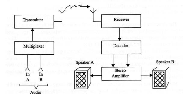
Our circuit can multiplex stereo signals coming from any stereo source, including tape decks, CD players, two microphones, etc. The reader can use the multiplex circuit with other transmitters such as described in this book, and all of them can send the multiplexed signal without encountering any problems.
You only need to wire the multiplexer between any transmitter and a stereo audio source to achieve conventional stereo transmission.
The uses suggested for this transmitter are the following:
It can be used as a wireless tape deck or CD player, sending signals from a fixed source to an FM receiver in a car or to a portable (Walkman®) FM re- ceiver by the pool.
It is useful in experimental radio stations for schools or clubs, sending various stereo programs to portable receivers.
How It Works
Figure 2 shows a block diagram of our stereo transmitter.
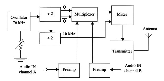
The multiplex oscillator runs at 76 kHz, and this circuit provides the synchronism signal to the multiplexing process. The configuration is based on an RC circuit to allow easy adjustments. The RC circuit is wired to one of the four gates existing in a CMOS IC 4093. This circuit must be adjusted by P1 to run at 76 kHz.
The signal produced by this oscillator is a square wave and is applied to the input of the other gate of the 4093 IC, which is used as a buffer/inverter. From this point, the output of the circuit is applied to a 4013 CMOS IC that consists of a dual J flip-flop. This circuit divides the frequency by two and four, providing two in-phase opposition 36 kHz signals and a 19 kHz signal.
The multiplexing circuit that follows this stage is based on two of the existing analog/digital switches of a 4066 IC. You can also use the equivalent IC 4016.
The 4066 is better than the 4016 IC, as the resistance in the on state presented by the switches is lower. This means less attenuation to the audio signals that must be multiplexed, but the difference is not significant when working with strong audio signals.
The switches are electronically activated at the frequency of 38 kHz. So, in the first cycle, when one switch is closed, letting the signal pass from channel A, the other is open, blocking signals from channel B. In the next cycle, the first switch opens, and the signal from channel A is blocked, enabling the signal from channel B. This is shown in Fig. 3.
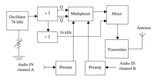
This means that the signals are cut and applied to the high-frequency carrier but are not mixed; their parts transmitted side-by-side. This means that, using the “inverse” circuit in the receiver, it is possible to recover the original signal of each channel.
The multiplexed signals to be applied to the transmitter stage must be mixed to a 38 kHz signal coming from R2, synchronizing the receiver. This is the signal that, when recognized by the receiver, makes the stereo LED light up.
The signal coming from the audio sources passes by a simple one-transistor amplification stage.
To avoid problems with high-frequency switching, which in some cases can generate noise in the receiver, it is necessary to add a lowpass filter to the circuit.
This is simply a capacitor, from 100 pF to 0.022 µF, wired between R14 and the ground.
The high-frequency stage that produces the radio signal is a simple one-transistor oscillator. We are using the BF494 as the core of this circuit, but the reader can replace it with more powerful stages.
Some components in this stage have values that depend on the power supply voltage. The values for a 12 V supply are in parentheses. The others are indicated for a 6 V power supply.
Assembly
Figure 4 shows the schematic diagram of the transmitter.
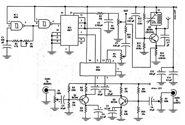
The components are placed on a printed circuit board as shown in Fig. 5. The use of DIP sockets is recommended for mounting the integrated circuits.
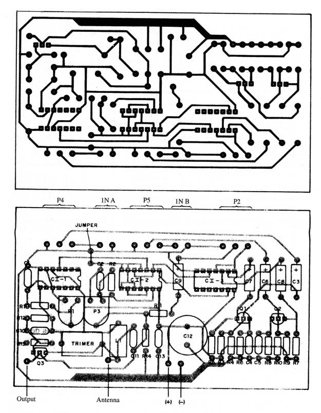
The trimmer potentiometer is a common variety, but for more accurate adjustment, you can use a multi-tum type with proper alteration of the printed circuit board layout. The potentiometers are linear or logarithmic and must be placed in the transmitter’s front panel for easy access.
The coil is formed by four turns of AWG 18 to 22 enameled wire over a core-less form 1 cm in diameter. You can use a pencil as the reference to wire this coil.
Any porcelain or plastic trimmer capacitor in the range between 2-20 to 4~40 pF can be used here. The reader must measure the distance between the component’s terminals and alter the printed circuit layout if necessary. For this reason, it is best to have the trimmer in hand before etching the printed circuit board.
Any piece of rigid wire between 8 and 40 inches in length can be used as the antenna. You can also use a common telescoping antenna found in any non-operating transistor radio. The antenna can be wired to different taps in the coil, as described in previous projects, to find the best performance.
For audio input, RCA jacks are used or as dictated by the signal sources. The jacks must be wired to the printed circuit board and potentiometer using shielded cable to avoid hum. You can also use a stereo jack if the plug used to apply the audio signals is compatible.
The power supply can be AA cells or a battery, depending on the version (6 or 12 V). If you have to use an aC-powered supply line, it is important to obtain a power supply that offers good filtering and regulation.
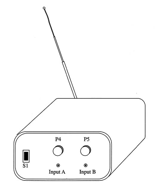
If you intend to use the transmitter for long time periods, it is important to increase the battery capacity. We recommend the use of C Or D cell in this case. A suitable plastic box for installing the unit is suggested by Fig. 6.
Adjustments and Use
It is important to have available an FM stereo receiver with a stereo LED indicator. First, we tune the receiver to a free point in the FM band. The receiver must be placed 3 or 4 ft away from the transmitter antenna.
Second, we turn on the transmitter and adjust the trimmer capacitor to tune the signal. Take care to tune in the fundamental and not harmonic signals. Next, we need to adjust P3 and P2 to the medium point of their range.
After this, we adjust trimmer potentiometer P1 until the stereo LED in the receiver glows. At this point, the multiplex circuit is operating in 38 kHz as needed by the receiver’s decoder stages.
Next, slowly reduce the pilot signal amplitude by adjusting P2 while you fine tune the trimmer setting. The ideal point in this adjustment is when you obtain a narrow band tuned by the receiver in which the stereo LED is on. At this time, we can plug a stereo source, such as a tape deck, signal generator, or two microphones, into the inputs. By opening potentiometers P4 and P5 and also adjusting P2, we obtain the best stereo reproduction in the receiver.
If high-frequency noise remains in the transmission, we must wire a capacitor in the range of 0.01 to 0.1 µF between the emitter of Q4 and ground. After all these adjustments are complete, we can use the transmitter. While in use, none of the adjustments can be changed, except P4 and P5, which can be adjusted according to the signal source power.
The multiplexer stereo encoder can be used with high-power transmitters. The signal must be picked up from the external modulation point shown in the diagram. In this case, the transmitter stage must be deactivated, and R14 must be removed from the circuit, as is transistor Q3.
Semiconductors
IC-l - 4093 - CMOS integrated circuit, four NAN D Schmitt gates
IC-2 - 4013 CMOS integrated circuit, dual J flip-flop
C1-3 - 4066 or 4016 CMOS integrated circuit, 4 analog/digital CMOS switches
Q1, Q2 - BC548 or equivalent general-purpose N PN silicon transistor
Q3 - BF494 high-frequency NPN transistor
Resistors (1/8 W, 5%)
R1 - 4,700 ohm-yellow, violet, red
R2 - 10,000 ohm -brown, black, orange
R3, R9 - 220,000 ohm-red, red, yellow
R4, R10 - 33,000 ohm-orange, orange, orange
R5, R7 - 12,000 ohm-brown, red, orange
R6, R8 - 6,800 ohm-blue, gray, red
R11- 22,000 ohm-red, red, orange
R12 - 8,200 ohm-gray, red, red
R13 - 5,600 ohm-green, blue, red or 8,200 ohm-gray, red, red
R14 - 68 ohm-blue, gray, black or 100 ohm-brown, black, brown
P1 - 10,000 ohm-trimmer potentiometer
P2 - 47,000 ohm-potentiometer
P3 - 100,000 ohm-trimmer potentiometer
P4, P5 - 100,000 ohm potentiometers
Capacitors
C1 - 680 to 820 pF ceramic
C2 - 2,700 pF ceramic
C3, C6, C7, C8, C9 - 10 µF/12 WVDC, electrolytic
C4, C5 - 0.1 µF ceramic
C10 - 0.01 11F ceramic
C11 - 4.7 or 5.6 pF ceramic
C12 - 470 µF/ 12 WVDC, electrolytic
C13 - 0.1 µF ceramic
CV - trimmer capacitor (see text)
Additional Parts and Materials
L1 coil (see text)
Printed circuit board, input jacks sockets, knobs to the potentiometers, shielded cables, Wires, plastic box, battery holder or power supply, telescoping antenna, solder, etc.


