If the sensor wired to this transmitter is triggered on, an alert signal will be emitted that can be received by any FM transmitter placed at a distance up to 300 ft.
Features
Power supply: 6 Vdc, 4 AA cells
Operation frequency: 88 to 108 MHz
Range: up to 300 ft (basic version)
Alarm signal: audio tone between 100 and 2 kHz
This circuit can be used to monitor remote sensors such as alarm sensors, cage sensors, switches placed in doorways, etc. If the sensor is closed or opened (depending on how it is connected), it triggers an oscillator that modulates the high frequency signal emitted by the transmitter.
Several interesting applications are suggested, as follows:
It can be used as a wireless car alarm. The transmitter will be activated, sending a signal to a remote FM receiver when someone tries to start the engine or open the door. The alert signal can be picked up by a bedside FM radio.
For espionage, it can detect when an enemy is coming. A sensor can be placed in a strategic place to activate the transmitter when an intruder is detected.
The transmitter can be used to send a signal when a cage door is opened by an escaping animal, or when the door of a trap is closed after an animal is captured. The receiver can be placed at a secure distance.
A building can be protected against intruders by installing sensors in the doors and windows. Any intruder will trigger the circuit, sending an alert signal to your FM receiver.
How It Works
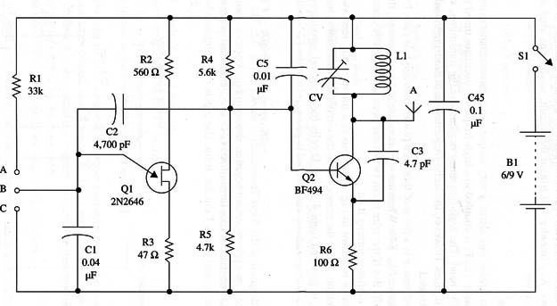
The basic idea behind this alarm is very simple. An audio oscillator using a unijunction transistor (UJT) is coupled to a high-frequency oscillator tuned to a free point in the FM band. The high-frequency oscillator is the transmitter, which is on the air at all times. However, the audio frequency oscillator triggers only when a sensor is activated.
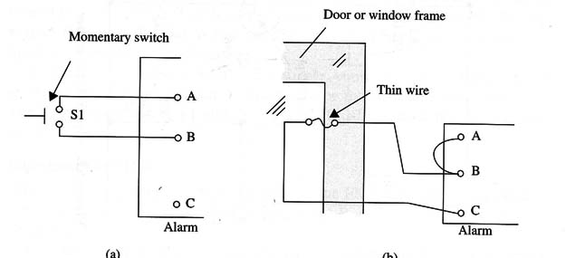
The simplest sensor is a piece of thin wire placed between two nails fixed in a doorway as shown Fig. 1b. When the wire is connected in the circuit, the audio oscillator is off. But if the wire is cut (when the door or window is opened), R1 will bias the oscillator, turning it on.
Another sensor is shown in Fig.1a. This is a microswitch, reed switch, or simple push button. When the sensor closes the circuit, the oscillator is biased on.
The circuit is powered from 4 AA or D cells for electrical autonomy. If it is used in a car, a voltage reducer can be used to power it from the 12 V battery.
Assembly
A schematic diagram of the Alert Transmitter is shown in Fig. 2.
The components are placed on a printed circuit board as shown in Fig. 3.
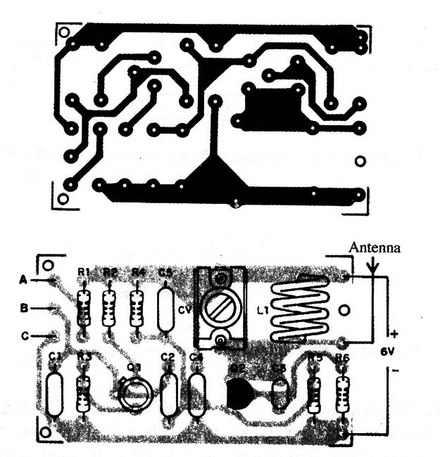
The coil (Ll) consists of four turns of AWG 18 to 22 enameled or plastic-covered rigid Wire wound over a 1 cm dia. form. Use a pencil as reference for winding this coil.
Any trimmer capacitors with capacitances ranging from 2-20 to 4-40 pF can be used. Plastic or porcelain types are suitable for this project. The antenna is a piece of rigid wire 10 to 30 in. long or a telescoping antenna.
Q1 is a unijunction transistor (UJT). The reader must be careful when installing this transistor. If it is placed in inverted position, the circuit will not operate properly.
The original transistor for 6 V applications is the BF494 or an equivalent such as the BF495. But if the reader wants a more powerful circuit, it can be powered from 9 to 12 V supplies. In this case, replace Q1 with a 2N2218 or BD135, and replace R6 with a 47 ohm X 1 W resistor. The signals can be picked up at distances up to 900 ft with these modifications.
To power the 6 V circuit from a 12 V supply, you can use the voltage reducer shown in Fig. 4.
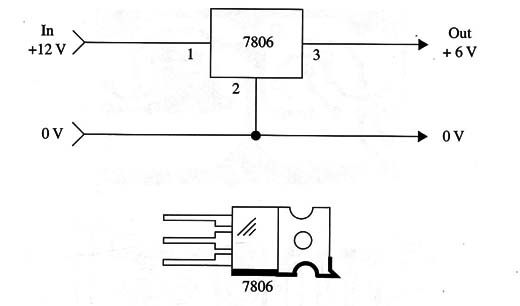
The integrated circuit must be mounted on a small heat sink. The circuit can be plugged into the car’s electrical system using the cigarette lighter socket.
Adjustment and Use
Place an FM receiver tuned to a free point in the FM band near the transmitter.
Connect a piece of wire between points A and B, and turn on the transmitter power supply.
Tune the circuit with the trimmer capacitor (CV) until you have the strongest signal in the receiver. If you don’t like the sound of the audio tone coming from the radio, you can change the value of R1. Values between 22,000 and 100,000 ohm can be tested. You can also replace this resistor with a 100,000 ohm trimmer potentiometer in series with a 10,000 ohm resistor to adjust the tone more precisely.
When the piece of wire between points A and B is disconnected, the radio signal tuned to the receiver frequency continues, but the audio signal does not.
Figure 5 shows how the sensor can be wired to the circuit.
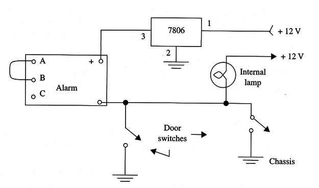
You can use normally open (NO) sensors or normally closed (NC) ones, depending on how you want the circuit to operate. The wires to the sensor can be very long (up to 300 ft) without causing operational problems.
In Fig. 5, the circuit is arranged for use as a remote car alarm. When one of the door-activated switches is closed, the courtesy lights are turned on, and the circuit begins to send the alert signal to a remote FM receiver.
Semiconductors
Q1 - 2N2646 unijunction transistor (UJ T)
Q2 - BF494 or equivalent high-frequency, small-signal NPN transistor (see
text)
Resistors (1/8 W, 5%)
R1 - 33,000 ohm-orange, orange, orange
R2 - 560 ohm-green, blue, brown
R3 - 47 ohm-yellow, violet, black
R4 - 5,600 ohm-green, blue, red
R5 - 4,700 ohm-yellow, violet, black
R6 - 100 ohm-brown, black, brown
Capacitors
C1 - 0.047 µF ceramic or metal film
C2 - 4,700 pF ceramic
C3 - 4.7 pF ceramic
C4 - 0.1 µF ceramic
C5 - 2,200 µF ceramic
CV - trimmer capacitor (see text)
Additional Parts and Materials
L1 - coil (see text)
B1 - 6 V, four AA, C, or D cells or voltage reducer from the car’s battery
A, B, and C isolated terminals
Printed circuit board, battery holder, plastic box, sensors, antenna, wires, solder, etc.


