The advantage is that the device presents very high input impedance and the characteristics of commutation or control of a bipolar transistor.
IGBTs are used in the same functions where power bipolar transistors and power FETs are used, and in some cases they have advantages They are used in applications where it is necessary to drive a high current load (solenoids, Iamps, motors, etc).
Symbol
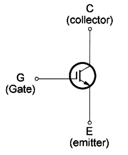
Figure 1 shows the symbol of an IGBT.

As with other transistors, we can,t identify an IGBT only by its appearance because it Iooks the same as bipolar transistors and power FETs. It is necessary have a part number or a schematic diagram of the equipment.
Specifications
IGBTs are identified by a part number. From the part number, theelectrical characteristics can be discerned. The main characteristics are as follows.
A. Maximum voltage between coIIector and emltter-the maximum voltage that can be applied to the device. It is also represented by Vce (max).
B. Maximum coIIectorcurrent-the maXImum current that can be conducted by the deVIce. It is also abbreviated by Ic (max).
C. Dissipation power-the maximum amount of power that the device can convert in heat and transfer to the surrounding area. It is given in watts and abbreviated as Pd (max) or Pd.
Where they are found
IGBTs are components widely found in industrial applications. The advantages of the use of this device in the control of high-current Ioads in industrial machines, such as motors, solenoids, electromagnets, and heaters, make them very commonly used in these types of equipment.
In many cases, the IGBT can directly replace a power FET or a Darlington bipolar transistor. The most the technician must do in many cases is change the value of some resistors in the circuit.
As IGBTs are new devices they are not very common in electric or electronic applications more than 10 years oId. ln home appliances, such as dishwashers, clothes washers, and others that use inductive Ioads, the IGBT can be found as the control element.
Testing
The simplest way to test an IGBT is measuring the resistance between the terminals. The resistance between the ate and the other elements in both must be very high. A low resistance in these measurements indicates a shorted device or one with loses.


