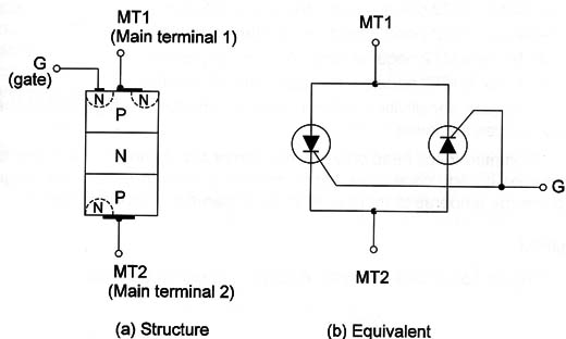
Compare a triac to two SCRs connected in inverse parallel (anti-parallel) and placed inside a single three-terminal case as shown in Figure 1.
The triac is indicated to applications where AC voltages must be controlled meaning that a large range of applications in domestic and industrial installations includes this component. So, it is another device with a large degree of importance for the reader. In basic applications the triac is connected in a circuit as shown in Figure 2.
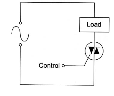
Like the SCR, the triac can be used as a power switch controlling a large amount of alternating current from the main terminals (MT1 and MT2) from a low voltage applied to the gate.
Unlike the SCRs that need only a positive voltages applied to the gate to be turned on, triacs can be triggered either by a positive or a negative gate signal, regardless of the polarities of the main terminal voltages.
This means that the device can be triggered by four modes, indicated as follows:
l+ Mode = MT2 positive and gate current positive
l- Mode = MT2 positive and gate current negative
lll+ Mode = MT2 negative and gate current positive
III- Mode = MT2 negative and gate current negative
The gate sensitivities in the l+ and lll- modes are high and in the other modes are lower.
Common triacs need only some miliamperes of current in the gate to be turned on and once in the conductive state, high currents in the range from some amperes to more than 1000 amperes can be controlled.
Symbol
Figure 3 shows the symbol adopted to represent a triac.
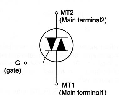
The body is the same as that used by high-power transistors, SCRs, and many other components. Notice that they are basically high-power solid-state switches and must be mounted in heat sinks when handling high currents.
The identification of the terminals (MT1, MT2, and G) is made using the information of the data sheet or documents of the manufacturer as it changes from type to type. A general rule is that MT1 used to be connected to the case or to the tab.
Specifications
The triacs are identified by a part number displayed as a figure on the body, the same way the SCRs, transistors, and many other solid-state devices are. From the part number, using a data sheet or othe document from the manufacturer, it is possible to find the electrical characteristics of the device.
The inverse procedure is valid as well; from the characteristics, it is possible to find a triac suitable to an application by the part number.
The main specifications to be observed in a triac are:
A. Maximum voltage-the maximum voltage that can be applied to the triac in the off state. They are indicated also as the Repetitive Pulse Reverse Voltage (Vrrm) or Repetitive Peak Reverse Voltage (Vrrm) and can be typically in the range between 50 and more than 1000 volts for common types.
B. Maximum current-the maximum current that can be controlled by the device is indicated as the Continuous On State Current or average On State and can be in the range of 1 ampere to more than 100 amperes for common types.
C. Trigger current and voltage-the current that triggers the triac on is indicated as the Gate Trigger Current and abbreviated by lgt. Typically this current is in the range between some microamperes and 100 mA depending on the size of the device. The trigger voltage is also indicated as Vgt and is typically in the range between 0.8 and 1.5 volts for common types.
D. Dissipation power-When the triac conducts the voltage across, it is typically between 1.7 and 2.2 volts. This voltage times the controlled current or the load current gives the dissipation power of the device.The maximum dissipation depends on the device.
Where they are found
Triacs are found in all the modern applications where a speed, temperature, or power control must be made from an AC power line voltage.
We can say that triacs are solid- state switches with a large range of applications in AC control.
Dimmers, speed motor control of electric appliances, heaters, and many other circuits use triacs as a central element.
Figure 4 shows a typical power control or dimmer for loads powered from the AC power line using a triac.
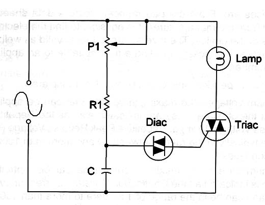
The operation principle is the same as the power control using SCRs described in other aticle in this site (See – SCRs – How they work).
The only difference is that the capacitor charges with both semicycles of the AC voltage and the triac triggers with them conducting both to the load.
The waveforms in the circuit are shown in Figure 5.
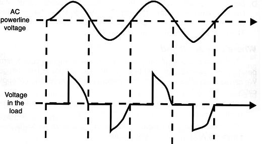
The diac is an auxiliary element used to help the triac trigger with the orrect voltage adjusted by the potentiometer. Circuits like this are used in ommon incandescent lamp dimmers replacing common on-off switches.
The speed control of motors used in electric appliances, such as drills and fans, use a circuit like this.
Testing
The best way to test a triac is using an appropriated circuit for this task. The multimeter can only reveal if a triac is shorted. If a low resistance 5 measured between MT1 and MT2 in a triac out of a circuit it is because is shorted.
When replacing a triac by an equivalent type, the specifications (voltage and current) must be equal or greater than the original.


