The basic idea of the integrated circuit (IC) originated from these questions:
1. Why do we have to manufacture all the components of a circuit in a separated process and then assemble them together to create the desired configuration?
2. Why not make them together in a unique silicon chip to perform the basic circuit for equipment using a single process?
The answer to these questions resulted in the integrated circuit or IC. The integrated circuit consists of a tiny silicon chip that houses a determined number of components, such as transistors, resistors, capacitors, and diodes, interconnected by conductive paths that act as wiring. The components and paths are formed by a complex process that includes diffusion, photo printing, and etching.
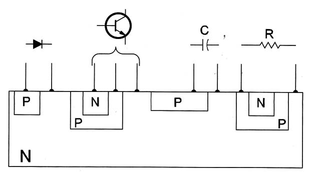
Figure 1 gives an idea how the many components can be created on a silicon chip.

In an N substrate, P regions are created forming a diode. If in the P region of a diode, another N region is formed, a transistor will be created.
A capacitor can be formed by a large P region. Having a reverse bias at the junction to create a capacitor, the junction will act as the dielectric and the PN regions as places similar to the varicaps. A resistor can be formed by a P channel formed in the N region.
The width and length of the channel determine the resistance of this resistor. The number of components, their disposition in the chip, and the wiring are planned to perform as a complete circuit such as an amplifier, a voltage regulator, or even a computer.
It is possible to house in a single chip, circuits with few components for simple functions to circuits containing more than 500 million components, such as in modern microprocessors used in personal computers. Even a complex integrated circuit with millions of transistors has a tiny footprint measuring only in millimeters.
The principal advantage of the integrated circuit is that the circuit can be manufactured almost complete, needing only a few complementary support devices to perform in the desired equipment.
For example, it is possible to create an IC containing a complete audio amplifier that needs only the input jacks, the power supply, the volume control, and the loudspeaker to perform the complete equipment.
The integration has some limits. Some components exist that can’t be easily integrated on a silicon chip. For instance, large-value capacitors and inductors are components that can’t be found in integrated circuits. So, when planning a complex integrated circuit, if large-value capacitors are needed, they must be external, and the common traditional discrete type must be used.
Although the integrated circuit is very important as a simplified solution for projects it can’t form a complete piece of equipment or circuit in many cases, needing completion with external components as capacitors and inductors.
Since an IC can contain practically any configuration with any number of components, they exist in a very large number of types and functions.
Symbol and Types
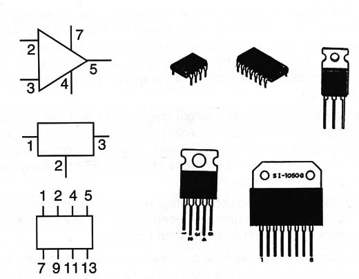
Figure 2 shows the common symbols adopted to represent an integrated circuit and its various types.

At the side of the lC’s symbol or inside, an identification figure allows the technician to identify it.
The number of terminals varies according the function. Types with number of terminals ranging from eight to more than 40 are used in common functions. Types with more than 200 terminals are found in special applications such as computers.
Figure 2 shows the most common types of ICs, found in many pieces of electronic equipment that use DlL (Dual In Line) and SIL (Single In Line) cases.
See the number of the terminals starting from a mark or point in the case. The identification of the terminals is very important when replacing an IC with another or when trying to troubleshoot. Voltage measurements must be made in these components. Some integrated circuits that perform high-power functions like motor controls, voltage regulators, and audio amplifiers are equipped with tabs or resources to allow them to be on heat sinks.
Specifications and Types
Today we can say that there exist millions of different types of integrated circuits. They are identified by a part number. Only with specific information about the part number is it possible to know what an IC is and what it does. The electrician who wants to work with electronic components doesn’t need to have complete handbooks or manuals of all the integrated circuit as it is impossible.
Common functions
Some integrated circuits contain a configuration simple enough and useful enough to allow them to be used in a large number of applications.
So, these circuits act as basic blocks in many projects and can be found not only in one kind of application, but in a large number of applications. For example, an integrated circuit that contains a simple low-frequency stage with some transistors and some other components can be used in an audio amplifier, a low-frequency oscillator, an alarm, a motor, and many other circuits.
Many types of these general-purpose or common-function integrated circuits were created and many of them became popular and are used in all the applications we can imagine. Electronics magazines that give projects to hobbyists indicate those le in their projects as they can be found in any electronic parts shop and can be handled easily.
The common functions found in le are divided in two other groups:
Analog
Analog integrated circuits are the ones that work with DC and analog signals, such as audio, video, AC, and others. We define as an analog quantity, one that can assume any value between two limits.
An AC voltage is an analog quantity as its amplitude can assume any value between zero and the maximum amplitude. On the other hand, a digital quantity can assume only determined values between two limits. A byte can assume only the integer values between 0000 0000 and 1111 1111.
In the group of analog ICs we can find some functioning as voltage regulators, operational amplifiers, comparators, audio amplifiers, video amplifiers, timers, PLLs, etc. It is interesting to give a brief description of each of these le as they are very common in many appliances and will be found by the reader in electric installations and in many AC-powered appliances.
Voltage regulators
The purpose of a voltage regulator is to maintain constant the voltage in a circuit. The power supplies of many pieces of equipment use this type of IC to have a regulated output supply voltage.
A voltage regulator, such as the 78XX and 79XX series or family (where the XX is replaced by a number indicating output voltage), is very common in appliances. For example, the 7806 furnishes a 6 V output under 1 A of current (maximum). Another type of voltage regulator is the one used in SMPS (Switch-Mode Power Supplies) and the ones found in computers, video monitors, and many other modern appliances.
The operation principles of these regulators are different from the linear regulators as they acts as oscillators, producing a voltage that depends of the frequency and pulse width of the output signal.
Symbols and Types
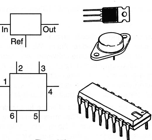
Figure 3 shows the symbols and some types of this lC. Notice that many of the le used as voltage regulators have resources to be mounted on a heat sink. Observe also that other le can have more than three terminals.

Specifications
The lCs used as voltage regulators, like any other IC, are specified by a part number. The electrical characteristics are found in data sourced by the manufacturer. The main specifications of these kind of IC are:
A. Input voltage range-the range of voltages that can be applied to the input. In the documentation it can be abbreviated by Vin.
B. Output voltage or range (Vout)-Some le are fixed voltage regulators. They have an internal zener that fixes the output voltage. Other have resources to be programmed by an external zener or resistors to a determined output voltage.
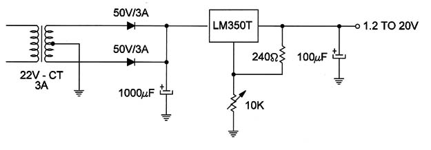
Figure 4 shows a circuit, the LM350, which is an adjustable voltage regulator for a large range of voltages and output currents up to 3 A.

C. Output current-the maximum output current that can be regulated by the IC is an important parameter to be observed when using this kind of IC.
CI.
Where they are found
Voltage regulator le are present in almost all equipment plugged to the AC power line and even in battery-powered circuits acting as voltage reducers.
After rectifying and filtering, they convert the AC power line voltage in one or more DC voltages necessary to power the electronic circuits.
These le are present in the first stage of any equipment or “power supply” stage.
Testing
The simplest way to test this kind of circuit is measuring the input and the output voltages. The multimeter is the instrument recommended for this task.
To know more about Integrated Circuits:
ART136E – Operational Amplifiers
ART204E – Integrated Audio Amplfier
ART205E – Digital Integrated Circuits


