The presence of electric charges in an ambient, a subject, or an object during a paranormal experiment can reveal important facts that are useful to the researcher.
Can a subject alter the electric charge of a part of his body during a PK experiment? Is the electric charge of the ambient around the subject affected when he achieves the fourth state of consciousness or trance?
These questions can be answered if the experimenter has a device that can detect electric charges, i.e., an electroscope. The electroscope described here is extremely sensitive and, at distances of up to a meter, can detect the static electric charges produced when, e.g., you rub a pen against your clothes.
The electroscope can be used in several paranormal experiments as suggested below.
Experiments
Placing the electroscope near the subject of a PK experiment, it is possible to detect any change in the ambient electric charge. Another interesting experiment can be made by connecting the electroscope to an object.
The researcher can detect, via the electroscope, if the electric charges in this object can be changed by willpower. The subject will try to alter the indication of the electroscope using his mental powers.
The object can be wired to the input of the circuit, and the subject must alter the properties of the object or move it across the surface of a table. The researcher can monitor any changes that appear in the electric charges during the PK experiment.
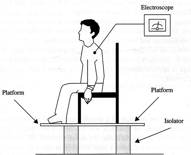
In any transcendental meditation and biofeedback experiment, monitoring the electric charge in the subject's body or in the ambient is important. The subject can try meditating while seated on an isolated platform as shown in Fig. 1.

The electroscope will indicate any change in his electric charge during the meditation state or trance.
The influence of a pendulum on any object or person can affect not only physiological states but also physical quantities not seen or felt by the researcher.
This includes the magnetic and electric helds produced by accumulated charges.
Changes in the electric charge can be detected by placing this device near the object or person or by connecting it to the object or subject. In the case of a human, the person can be placed in an isolated platform as suggested in Fig.1.
µFO researchers say that the presence of a flying saucer or any strange ship can alter magnetic and electric fields around them, causing interference in many appliances.
The presence of a µFO that is too distant to be detected by the malfunction of appliances still can be detected by an electroscope or a magnetic field detector.
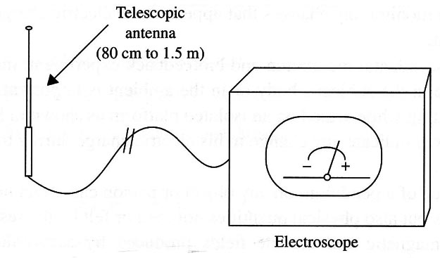
The circuit can be wired to a small antenna, as shown in Fig. 2, to detect changes in the atmospheric charge.

This circuit will also detect the presence of charged clouds passing over your home when a storm is forming.
Warning: Do not leave the circuit connected to the antenna during a storm, as it can act as a lightning rod!
In experiments involving the presence of ghosts or poltergeists, the electroscope is a powerful tool for detecting their presence.
How It Works
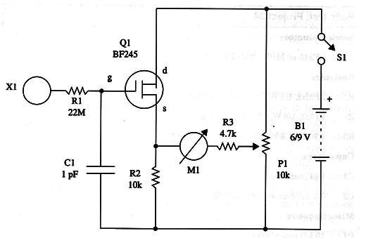
The current flowing between the source (5) and the drain (d) in a junction field-effect transistor (J FET) depends on the voltage applied to the gate (g). As the gate is isolated from the channel in which current flows, the device has a very high input impedance. This means that small electric charges in the gate produce electric fields that can control the current flow.
If an electrode is wired to the input of the circuit, any electric charge in this electrode can induce charges in the gate region and alter the current flow through the transistor. In the electroscope, the electrode is the sensor, and the transistor is wired to form a branch of a Wheatstone bridge.
Any change in the charges detected by contact or induction can alter the bridge equilibrium, as will be indicated by a current meter. The user has only to put the bridge in equilibrium and observe the meter indications.
A problem to be avoided is that high voltage applied to the gate of the transistor can burn it. The Spark between the gate and the channel region produced when high voltage is applied destroys the device. So never touch any charged object with the electrode!
->Assembly
Figure 3 shows the diagram of a simple paranormal electroscope. Any common JFET general-purpose transistor will function in this circuit. We recommend the BF245 as shown in the schematic.

If you use the MPF 102, the terminal placement is different, and the transistor must be inverted (Hat part down).
The ideal meter for this project is a 50 µA unit with zero in the center of the scale. This type of meter is used in some devices as a battery state indicator or VU meter. But if you canit find one, a common meter with full scale values between 50 and 200 pA can be used. You will just have to adjust the equilibrium point to a current other than zero when using the circuit.
The electrode is a loop of bare wire or a metal sphere. The circuit can be housed in a small box (plastic or wood) and used anywhere.
Testing and Using the Circuit
Install the cells or battery and turn on Sl. Adjust Pl until the needle of the meter reaches approximately the middle of the scale. Then rub a pen (plastic, spherical) over the surface of your clothes and place it near the electrode without touching it. The needle will move, indicating the presence of electric charges.
Note: remember that, on humid days, it is difficult or impossible to charge objects.
When using the circuit, you only have to adjust P1 to set the needle to the middle of the scale and observe any movement indicating the presence of charges.
Suggestions
Plug an external antenna into the circuit to detect charges in the air or in the clouds. The wire must be short in this application. If you canit find a meter suitable for this application, use your multimeter set to the lowest current scale.
The device can be installed inside a glass bottle, imitating the classic gold metal plate electroscope found in physics laboratories.
Semiconductors
Q1 - BF245 or MPF102 JFET (see text)
Resistors
R1 - 22 M, 1/8 W, 5% - red, red, blue
R2 - 10 k, 1/8 W, 5% - brown, black, orange
R3 - 4.7 k, 1/8 W, 5% - yellow, Violet, red
Capacitors
C1 - 1 pF, ceramic
C2 - 0.1 µF, ceramic or metal film
Miscellaneous
PI - 10 k - potentiometer
X1 - Electrode (see text)
M1 – 50 - 0 -50 µA microampere current meter (see text)
S1 - SPST, toggle or slide switch
B1 - 6 or 9 V, four AA cells or a 9 V battery
Terminal strip, plastic or wooden box, knob for P1, cell holder or battery clip, wires, solder, etc.


