There are several ways to implement biofeedback projects.
It is enough to have some kind of effect that can be controlled by the action of our body or mind. The two main types of biofeedback are visual and sound.
For example, in visual feedback, the controller must maintain the rhythm of a lamp blinking by finger pressure on an electrode, or by attempting to change the temperature of its own body, as shown in Figure 1.

In a sonic feedback, the emission of beeps from an oscillator can be controlled by the pressure of the fingers on an electrode, from the position of the hand on a light sensor or other resource.
See what feedback indicates that the controlled circuit feeds the operator in order to make it able control his/her effects.
There are several biofeedback circuits that can be assembled easily. Here are a few.
Visual Biofeedback
Electronic devices for relaxation, transcendental meditation, concentration, yoga, and other activities involving mental health and the human body itself are increasingly common.
Electronic biofeedback is one of the features that falls into this category and admits a large number of settings. The circuit we describe in this article is very interesting, both for its effects and for its ease of assembly.
This circuit has a visual feedback, that is, the operator's action on the circuit is fed back in the form of light pulses produced by two LEDs.
The operator must then control the pressure of his/her fingers on two pairs of electrodes in order to synchronize the blinks or to obtain blinks of the same frequency for the two LEDs so that one color does not predominate over the other.
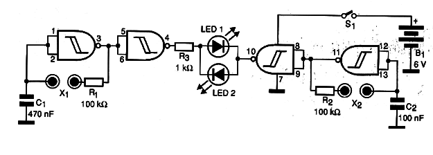
The circuit is made up of two oscillators controlled by the person's skin resistance, all built around the NAND gates of a 4093 integrated circuit.
In Figure 2 we have the complete diagram of the device that can be powered by 4 common batteries.
A printed circuit board for its preparation is shown in Figure 3.
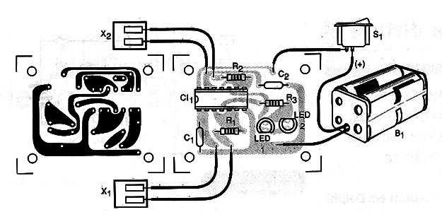
The electrodes consist of pairs of metal sheets or even coppered regions of a printed circuit board which must be touched at the same time with the fingers.
One electrode is used for the right hand and the other for the left hand.
An interesting possibility of use for this circuit is the exchange of the electrodes by NTCs of approximately 100 k Ω in order to obtain an action by the temperature of the body.
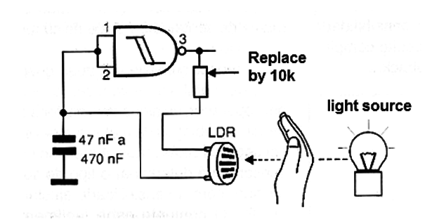
It is also possible to replace the sensors with LDRs in a configuration as shown in Figure 4, in which the person seeking the concentration should hold the positions of his/her hands firmly in order to control the amount of light that falls on these sensors and with that the frequency LED blinks.
If the frequency of the blinks is too high and the reader wants to change them, change the value of C3. Values in the range of 100 nF to 4.7 µF can be experienced.
Larger values will result in a decrease in the flashing frequency of the LEDs.
Sound biofeedback
In this circuit, the operator must control the sound emitted by a small speaker from the pressure of the fingers in a sensor.
The circuit is powered by batteries and the sound emitted by a small speaker. As the consumption is very low, the circuit can be used for long intervals of time.
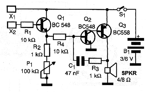
What we have in this project is an oscillator with two complementary transistors where the frequency is determined basically by C1.
This component can have its value changed over a wide range of values ??depending on the desired effect.
With large capacitors, for example, we can have a metronome effect in case the pulses of the circuit can be changed to synchronize with heart beats.
A control transistor (Q1) determines both the trigger point of the oscillator and the frequency, set at P1, which is a sensitivity control. In Figure 5 we have the complete circuit of this second biofeedback.
In Figure 6 we have a suggestion of assembly on a printed circuit board.
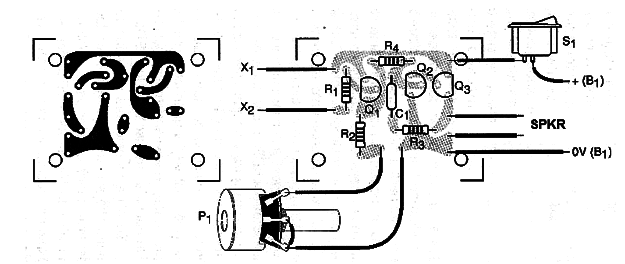
The sensor consists of two metal plugs that must be touched by the operator or two metal rods or metal tubes that must be secured by the hands.
The pressure on the sensors will determine the type of sound emitted, with the sensitivity set at P1. The assembly fits easily into a plastic box whose dimensions are basically determined by the size of the speaker used.


