Several experiments are suggested in the following articles, and some projects add special resources to the experiments for the experimenter who is looking for a different approach. There are also experiments involving sound and images in other paranormal areas such as ESP, psychometry, etc.
Sounds or images from the next dimension can be picked up, often when you least expect them, using the devices described next.
Project 16: Light-to-Sound Converter
When converting modulated light into sound using a sensor that is fast enough to respond to the changes, some surprising things can happen. For instance, if you point a sensor at a fluorescent lamp, you'll hear the 120 Hz signal of the modulated light, corresponding to the two instances in each power supply line cycle in which the voltage passes through zero volts. The gas inside the fluorescent lamp ionizes in each half-cycle of the power supply ac voltage and becomes inactive when the applied voltage between cycles crosses the zero point. If you point the same sensor to a white noise light source such as a small area of a TV screen, the sound produced is also a form of white noise.
Starting with this fact, a circuit that can convert modulated light into sound can be used in several experiments, not only when looking for paranormal voices but also to detect other paranormal phenomena such as ESP, psychometry, telekine-sis, clairvoyance, etc. The circuit can also be used to receive modulated light from a Kerr cell or a laser in a wireless audio link.
The project described here is a simple light-to-sound converter that will allow you to "hear the light."
How It Works
The sensor is any phototransistor or photodiode. These devices have a light-sensi-tive surface that is accessible through a small window in the transparent plastic package. Light falling onto the sensor produces free current carriers that can be picked up by the circuit. If modulated light is the source, the current will have the same wave shape.
These sensors are very sensitive and can even "see" light wavelengths that our eyes can't (e.g., infrared and ultraviolet). They are also very fast (many times faster than our eyes), "seeing" changes in light amplitude that we can't detect. Some photodiodes can "see" variations in light amplitude at frequencies up to 50 MHz.
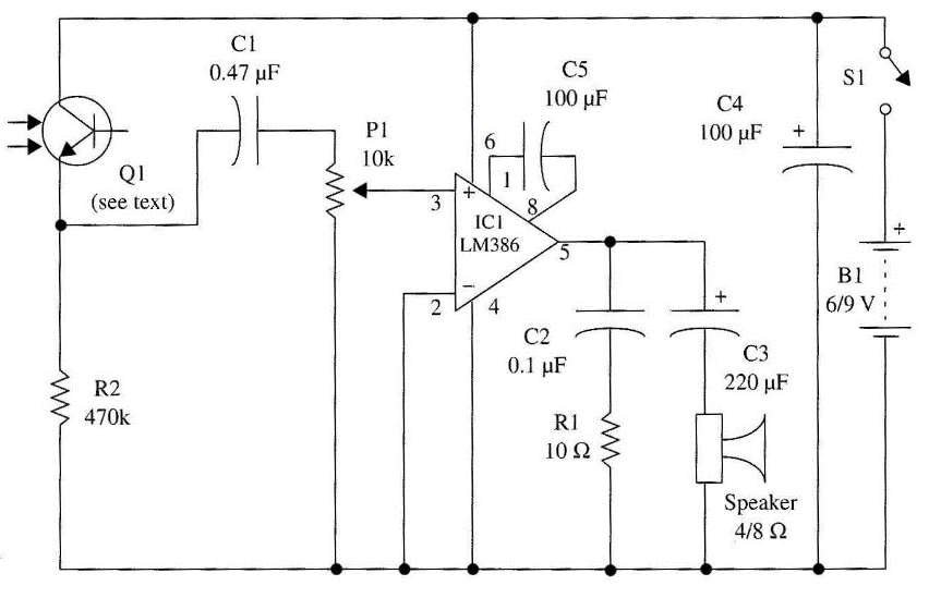
Applying an amplifier stage to the current, we can increase it to a level strong enough to drive a headphone or even a loudspeaker. The amplifier is formed by an LM386, an integrated circuit that can provide some hundreds of mill watts to a small loudspeaker or a headphone when powered from four to six AA cells.
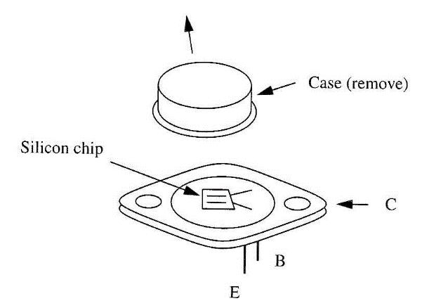
The gain of the circuit (about 200 times) is determined by C5. P1 acts as a sensitivity or volume control. An economical approach to building the sensor is the use of a common power transistor such as shown in Fig. 1.
By removing the metallic package to expose the chip, any silicon transistor can be converted into a phototransistor. Types such as the 2N3055 are sensitive enough to provide the circuit with a few milliamperes of current when illuminated. These components act as true photocells, converting light into electrical energy.
Assembly
The complete circuit of the light-to-sound converter is shown in Fig. 2. The circuit can be mounted as shown in Fig. 3.
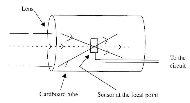
Any phototransistor can be used as the sensor. It is important to install the sensor inside a small cardboard tube to pick up light from only one direction. Another resource for improving circuit sensitivity is the addition of a convergent lens in front of the sensor, placed as shown in Fig. 80. With the addition of the lens, the circuit becomes very directional and can pick up light from small, distant light sources.
Any low-impedance (4 to 100 ?) headphone or even a 5 cm to 10 cm x 8 ohms loudspeaker can be used as final transducer to convert the signals into sound. You can point the sensor at a fluorescent lamp placed miles away from you and hear it using this circuit.
If a laser beam, placed at a distance of a few miles, is modulated by an amplifier, and if you use a microphone as an input to the amplifier, you can use this de-vice to hear anything that is spoken into the microphone. The light beam will act as a carrier for the sounds.
Using the Circuit
Turn on the power supply and point the photo sensor to a fluorescent lamp or to the screen of a TV receiver. The light signal converted into sound will be heard as a continuous tone. (In the case of TV, the sound you hear is the frame rate.)
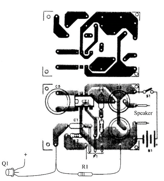
Alter the value of R2 to change the circuit characteristics to accommodate the sensor that you are using. Depending on the sensor, this resistor can assume values between 100 and 2,200 k?.
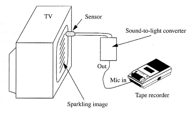
You can experiment with picking up voices from a noisy image in the TV screen by plugging the output of this circuit into a tape recorder as shown in Fig. 5 This figure also shows how you can use the sensor to directly drive the input of any audio amplifier (including the ones described in this book) or the in-put of a tape recorder.
Suggestions
? Infrared or ultraviolet filters can be placed in front of the sensor to obtain a selective frequency response to light sources.
? Placing moving objects in front of the sensor, such as the helix of a fan, a stroboscopic effect can be added to the experiments.
? Colored filters, made with pieces of sheet cellophane, can be used in some experiments.
? Point the sensor toward the sky, and the natural light will produce some strange signals—at night.
? Thunderstorms can be heard if you point the device at the sky to pick up lightning flashes.
Semiconductors
IC-1 LM386 integrated circuit, audio amplifier
Q1 Any phototransistor (TIL71, TIL81, TIL411, etc.) or photodiode (see text)
Resistors
R1 10 ?, 1/8 W, 5%—brown, black, black
R2 470 k?, 1/8 W, 5%—yellow, violet, yellow
Capacitors
C1 0.47 µF, ceramic or metal film
C2 0.1 µF, ceramic or metal film
C3 220 µF/12 WVDC, electrolytic
C4 100 µF/12 WVDC, electrolytic
C5 100 µF/12 WVDC, electrolytic
C6 10 µF/12 WVDC, electrolytic
Miscellaneous
P1 10 k? potentiometer SPKR 4 to 100 12 speaker or headphone
S1 SPST, toggle or slide switch
B1 6 to 9 V, four or six AA cells
Printed circuit board, cell holder, plastic box, convergent lens, cardboard tube, wires, solder, etc.

