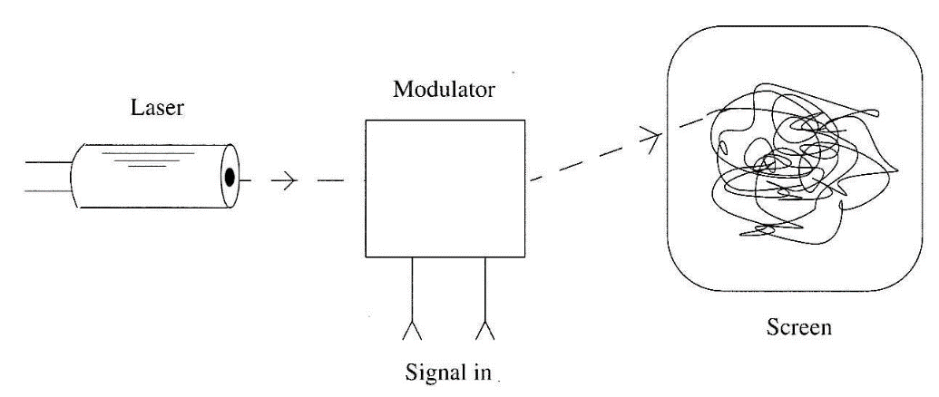
The basic idea is the use of a modulator to make the light beam change its direction according to signals from a sound source and then to draw figures on a screen, as shown in Fig. 1.

Using any signal or noise source in the modulation process, the figure produced in the screen can reveal strange forms when photographed. Of course, the circuit has other applications, such as for light shows, and it produces interesting visual effects when the modulation circuit is plugged to the output of an audio amplifier. Upgrading the circuit with a two-axis mirror control, the circuit can be plugged into the output of a processor to draw images on a screen.
How It Works
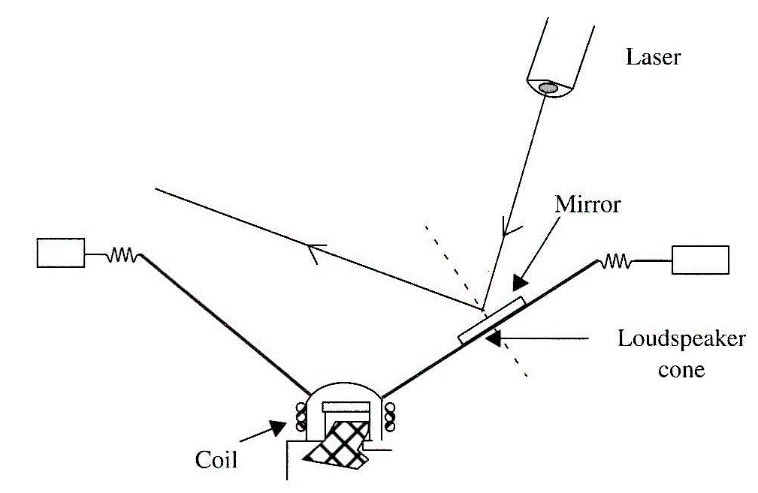
A small mirror is affixed to a loudspeaker as shown in Fig. 2. When the loudspeaker’s cone moves forward and back, the mirror changes its position, altering the reflection angle of the laser beam. As the cone's movement is fast, the reflected beam will draw random figures on a projection screen. If a photographic camera is placed in front of the screen with the shutter open (time exposure), the figures produced by the beam can be recorded on film.
Assembly
Using glue, affix a small mirror to the cone of a 4 to 6 inch loudspeaker. Super glue or an epoxy is recommended.
The loudspeaker is connected to the output of any low-power amplifier (0.5 to 5 W). Don't use high-power amplifiers, which can damage the loudspeaker if you turn the volume up too high.
In normal operation, you only need several mill watts to generate an image on a wall. The size of the image depends on the distance between the mirror and the wall.
The laser must be placed in a position that allows the beam to be pointed at the mirror and reflected to the wall or screen. A tripod or other stand can be used for this task.
Warning: Laser radiation is dangerous. Avoid direct exposure to the beam.
Using the Circuit
Point the laser at the mirror so that it produces a light point on the screen. The screen can be white cardboard or any white wall.
Plug the audio source into the input of the amplifier. Any of our noise sources can be used as an audio source in experiments involving EVP and EIP.
Adjust the audio amplifier volume control, starting from the minimum to pro-duce an image of the proper size. (The "proper size" depends on the distance be-tween the screen and the camera you will use to record the images.) To make experiments with a photographic camera, open the lens for a period of 15 to 40 seconds, registering the images in the interval. Other light sources in the ambient must be extinguished to avoid overexposing the film.
Remember that the loudspeaker doesn't have much high-frequency response. This limitation is a factor when working with high-frequency signals and also with white noise.
Suggestions
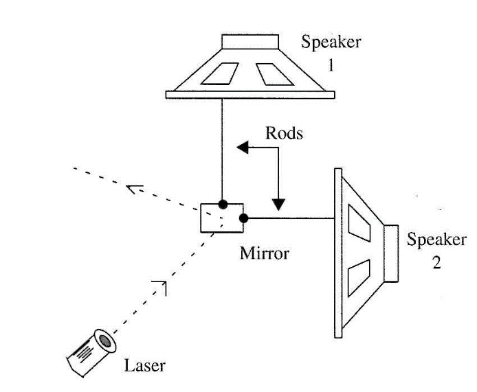
■ The mirror can be moved by two loudspeakers as shown in Fig. 96, combining sounds from two sources. In this experiment, the mirror will produce two-axis movements that are determined by the signals applied to the loudspeakers.
■ You can use other light sources in the experiments, such as colored spotlights, flashlights, etc.
■ Audio filters can be added in series with the loudspeaker (see experiments with EVP) to allow only specific frequency ranges to affect the experiments.
Observation
This circuit can be used for light shows in clubs or for other public events. It will produce dancing images when the loudspeaker is plugged into the output of the public address (or other) amplifier. If the loudspeaker is connected to a high-power amplifier, use a resistor (100 Ω to 1 kΩ) to reduce the applied audio power to safe levels.
Today we can count on MMD devices (Micro-mirror devices) for this application
SPKR 4 or 8 Ω x 4 or 6 inch (10 or 15 cm) loudspeaker
X1 Mirror (2 x 2 cm)
M Audio amplifier (see text)
L Laser source (laser pointer or neon laser)
Miscellaneous
Wires, video or photographic camera, screen, etc.


