The penetrating sound of the thunder sometimes creates the sensation that it comes from inside our head. This project is based on this fact, using a new concept of sound wherein the sensation of hearing is produced inside our brains. Although some researchers are trying to use this concept in audio (hi-fi) applications, including an author who published some articles about it many years ago, the brontophonic sound can also be used with other goals, including paranormal experiments as described here.
To give the reader an idea of what the brontophonic sound is, we begin by ex-plaining the familiar physical phenomenon called beat.
Beat
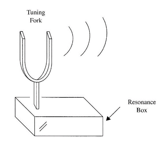
In your secondary school or physics lab, you may have learned about tuning forks such as the one shown in Fig. 1. When a tuning fork is struck, it vibrates at its natural frequency, which is determined by its size, material, and shape. The sound produced this way is called "pure," as it has a sinusoidal wave shape and a specific constant frequency.
An important phenomenon occurs when two different tuning forks (tuning forks tuned to different frequencies) are set to vibrate at the same place and at the same time. If you listen carefully, you'll not only hear the two basic tones (for which they were designed), you may also hear a much lower tone and a much higher tone as well. This phenomenon occurs when the two tones are mixed inside your ear, or specifically in the eardrum membrane.
One of the additional frequencies heard is a sum frequency, and the other is a difference frequency. If one fork vibrates at 800 Hz and the other at 300 Hz, it is very possible that you will hear a lower frequency tone of 500 Hz (800 — 300 Hz) and a higher tone of 1,100 Hz (800 + 300 Hz).

This phenomenon, caused by interference between sound waves, is called beat. Many electronic devices such as radios, TV, and telecommunication circuits, use the beat principle in their operation to lower the frequency of a signal to a value that can be used to drive the processing circuits.
If you examine how the two additional frequencies are produced (500 and 1,100 Hz), you'll find that the phenomenon occurs because each point of the ear-drum simultaneously receives vibrations from two different sources and has to vibrate at two frequencies at once. The result is a combined movement of each point of the eardrum that produces the two additional frequencies.
The important point to notice in this phenomenon is that the two new frequencies are not produced by the sound sources but are created inside the ear, or in a microphone, at any observed point in space.
Let's now go a step further and transpose the same concepts to ultrasonic sources, one of them operating at 19,000 Hz and the other at 20,000 Hz. (Re-member that we can't hear sounds at frequencies much above 18,000 Hz.)
The vibrations produced by either source separately can't be heard by anyone. But, when the two tones are mixed inside your ear, they produce two new tones. One of them, the sum tone of 39,000 Hz, is above our upper auditory limit, but the other, the difference tone of 1,000 Hz, is in the audible frequency range and can be heard.
The interesting part of this phenomenon is that, because the difference tone is produced inside your ear (or, more precisely, in your eardrum), you will have the strange sensation that the sound comes from inside your head, or that the sound comes from nowhere.
If the ultrasonic sounds are produced by high-power sources, the beat sound generated inside you will cause a certain discomfort, and exposure to vibrations of this kind can even cause panic or other psychological or physiological effects. (In some cases, it has been reported that very low-frequency beats can even cause dysentery!)
For the paranormal researcher, this kind of ultrasound source can be used in some fantastic experiments. An ambient can be filled from two ultrasonic sources and picked up by a microphone plugged into a recorder. The type of sound that can be heard when the tape is edited is a subject for discussion.
It is also interesting to see how this kind of vibration can affect or stimulate people with paranormal abilities or in ESP experiments.
How It Works
This project is formed with a pair of powerful ultrasonic modulated oscillators running in ranges between 18,000 and 25,000 Hz. A 4093 IC is used as basis of the project.
Each of the four NAND gates of the 4093 is wired as an oscillator. In the first block, we have IC1-a running in a very low frequency range (modulation circuit) given by R1 and Cl. This circuit modulates (in frequency) the second oscillator, made with the IC1-b NAND gate.
This oscillator runs in a frequency range between 18,000 and 25,000 Hz, given by C3 and adjusted by P1. The frequency-modulated signal produced by this circuit is applied to a high-power output stage using a power FET. As a load, the power FET uses a piezoelectric tweeter. Many common tweeters can reproduce sounds above our audible limit with good performance and therefore can be used as ultrasonic transducers. Common piezoelectric tweeters can produce several watts of ultrasonic sounds in the range up to 25,000 Hz. Pay attention to the characteristic of the tweeter you use, choosing one that can go up to 25,000 Hz or more.
The other low-frequency oscillator has its frequency determined by C5 and R7, and it modulates the fourth oscillator, made with IC1-d. This oscillator operates in the ultrasonic range and has its frequency adjusted by P2. The signal from the second ultrasonic oscillator also drives a power output stage with a power FET, and a second tweeter is used as transducer.
The circuit can be powered from 6 to 12 V sources and can fill an ambient with several watts of ultrasonic vibrations as described above. It is only necessary to place the tweeters a few meters apart to fill one ambient with different ultrasonic signals, producing the strange effects described in this section.
Warning!
Mammals such as dogs, cats, rats, et al. can hear not only the audible beat produced by this device, but also the ultrasonic sounds. These animals are made very uncomfortable by the sounds generated in this experiment. Don't use this equipment if they are present.
Some low-frequency beats that can occur with this device, in the range of alpha, beta, and theta brain waves, can induce epileptic seizures. Do not use this device in experiments that would require people to remain in the ultrasonic field during prolonged sessions! Avoid the use of this device near anyone who has a history of epilepsy. The very low-frequency beats can create additional physio-logical/psychological effects in humans and, in some cases, may even cause dysentery!
Assembly
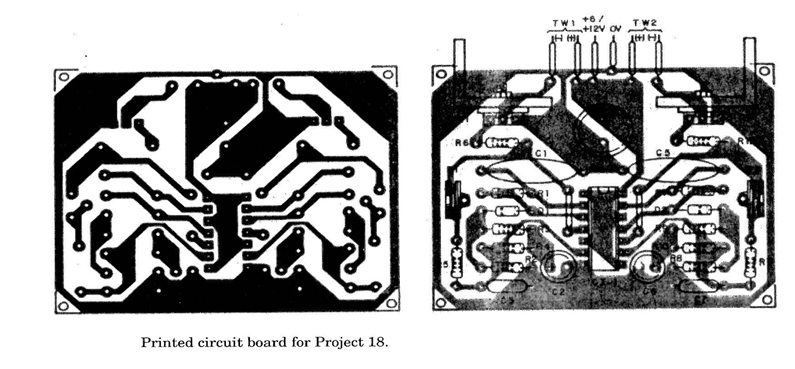
Figure 85 shows the schematic diagram of the brontophonic oscillator. The printed circuit board for this project is shown in Fig. 2.
Any P-channel power FET, rated to 4 A or more of drain current and voltages of 200 V or more, can be used in this project. Types of the IRF series, common in switched-mode power supplies such as found in computers, are cheap and suit-able for this project.
The transistors must be mounted on heatsinks. The heatsinks are pieces of metal, 5 x 8 cm, bent to form a "U" and screwed to the transistors.
The small tweeters, as shown in the figures, with power ratings of 50 W or more are suitable and can be plugged to the circuit with wires from 40 cm to 2 m in length. The tweeters must be placed as far apart as possible for best results.
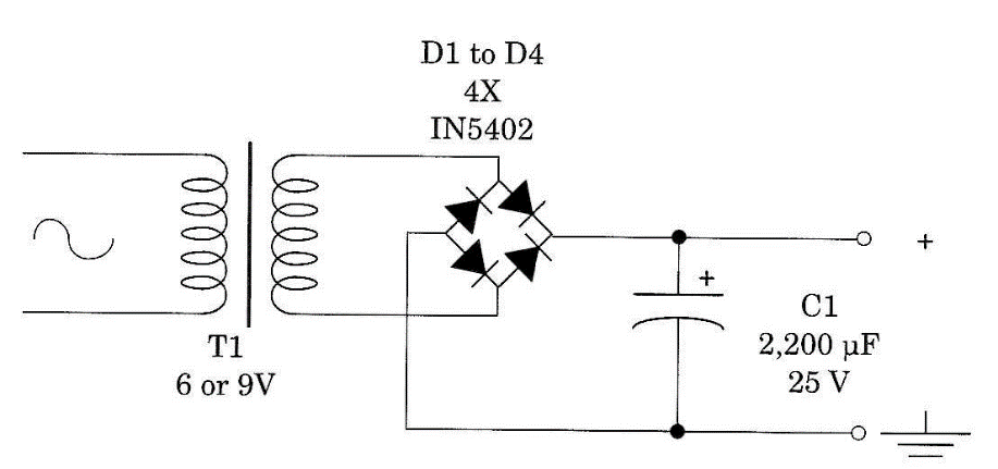
A power supply suitable for this circuit is shown in Fig. 87. The transformer has a primary winding rated to the ac power line voltage and a secondary rated to 6 to 9 V and 2 A of current.
The circuit can also be powered from four to six D cells. As the current drain is high, the continuous operation time when using cells is not long. A plastic or wooden box can be used to house the circuit.
Although, in the original project, we recommend trimmer potentiometers, the reader is free to modify the project to use common potentiometers placed in the front panel. This will allow the researcher to have additional control over the generated signal.
Using the Circuit
Place the two tweeters separated from each other by a distance of at least 2 m. Turn on the power supply. Adjust PI and P2 until you get the strange sensation of modulated sound being produced inside your brain. Do not expose yourself over a long period to this sound, as it can produce panic and other unpredictable dangerous effects.
Warning!
If using the equipment in experiments involving humans, take care and consult a specialist to avoid problems. Ultrasonic sounds and beats are dangerous and can cause problems that include the possible inauguration of an epileptic attack!

When attempting to pick up voices, do not remain in an ambient that is filled with the signals produced by this device.
Observation
The device can be used in alarm systems, as it can drive an intruder into a state of total discontrol and force him to leave before accomplishing his intent.
Suggestions
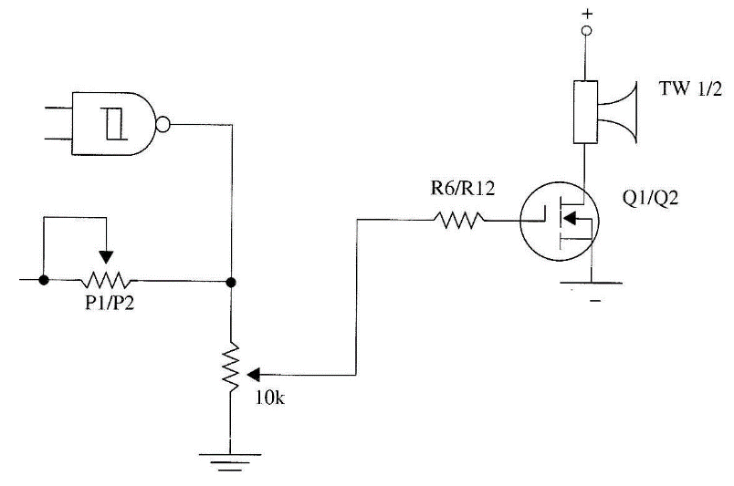
■ A volume control can be added as shown in Fig. 5. With this control, you can perform the experiments in the presence of humans without the discomfort of a high-power ultrasonic source.
■ Only one oscillator can be used in experiments involving pure ultrasound. You can add a switch in series with each tweeter to turn it on and off whenever you want.
■ You can add a switch to disable one or the other oscillator to perform experiments with only one ultrasonic source.
■ A special low-impedance ultrasonic transducer can be tested with this circuit. Depending on the transducer used, the frequency can be increased to more than 30,000 Hz.
■ The high-power ultrasonic signal produced by this circuit can scare birds from your property. You can conduct further experiments in this area.
■ In complex experiments, you can use more than one of these circuits to fill an ambient with a variety of ultrasonic sounds.
Parts List: Project 18
IC-1 4093, 4 NAND Schmitt Gates, CMOS integrated circuit
Q1, Q2 IRF640, IRF720, IRF620 or equivalent. Any power FET (field effect transistor) (see text)
D1, D2 1N4148, 1N914 or equivalent, silicon general-purpose diodes
Resistors
R1, R7 330 kΩ, 1/8 W, 5%—orange, orange, yellow
R2, R8 47 kΩ, 1/8 W, 5%—yellow, violet, orange
R3, R4, R9, R10 22 kΩ, 1/8 W, 5%—red, red, orange
R5, R11 4.7 kΩI, 1/8 W, 5%—yellow, violet, orange
R6, R12 10 kΩ, 1/8 W, 5%—brown, black, orange
Capacitors
C1, C5 0.22 µF, ceramic or metal film
C2, C6 0.1 µF, ceramic or metal film
C3, C7 2,200 pF, ceramic
C4 1,000 µF/16 WVDC, electrolytic
Miscellaneous
Pl, P2 100 kΩ potentiometers or trimmer potentiometers (see text)
TW1, TW2 Piezoelectric tweeters (see text)
Printed circuit board, power supply, plastic or box, heatsinks, knobs for P1 and P2, wires, solder, etc.


