To be useful as a feedback circuit, the "patient" must be able to control the tone produced by the device by changing his body temperature. But other experiments can be performed with this device such as described for the previous project. The use of a tone can free the person who is training or being observed to close his eyes and use only his ears to feel the temperature changes.
Experiments
The basic application for this circuit is as a training device or as biofeedback, helping the operator to achieve special mental or physiological states. The person must maintain the tone at a predetermined frequency or try to change it by modifying his physiological state.
As a monitoring device, the circuit can detect changes in the temperature of a human body or an object in PK experiments, as described in the previous project.
All of the experiments performed in the previous project can be repeated using this circuit.
How It Works
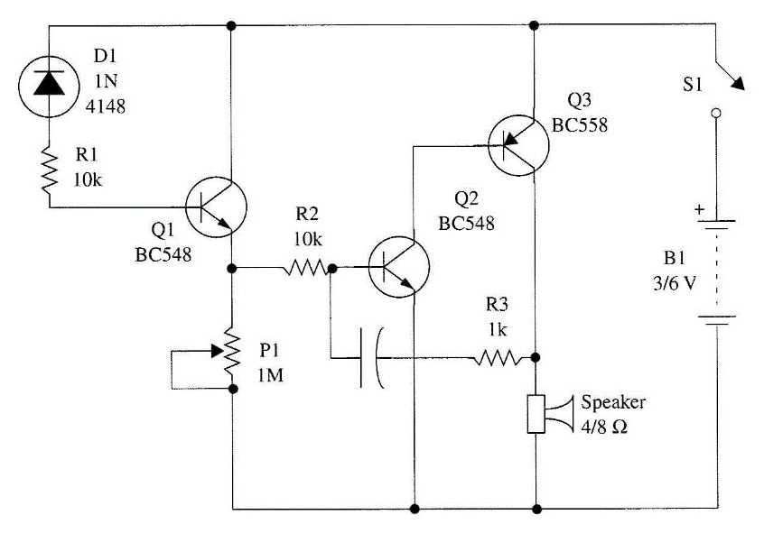
A general-purpose silicon diode is used as a temperature sensor, as in Project 25 (See note above.). The current flowing from the sensor is amplified by a transistor (Q1) and used to bias a two-transistor audio oscillator. In this oscillator, feedback that keeps the circuit in operation is provided by Cl. This capacitor, with the resistance represented by Q1, determines the operational frequency of the circuit.
Considering that the resistance of Q1 changes according the current biasing its base, which is determined by the temperature of the sensor, the frequency of the tone also is dependent on the sensor's temperature. R1 is used to adjust the sensitivity of the circuit and the central frequency of the tone in an experiment. The circuit is powered by two or four AA cells and uses common parts.
Assembly
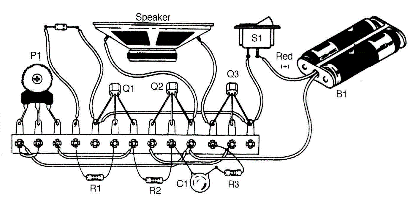
Figure 1 shows the schematic diagram of the temperature-controlled oscillator. Like the previous project, this is also very simple and appropriate for the reader who is less experienced with electronic assembly, and it uses a terminal strip for mounting the components (Fig. 2).
Keep the wires and component terminals short to avoid shorts. The wire to the sensor can be as long as 40 cm. Avoid the use of longer wires, which can pick up noise that affects the circuit operation.
Any general-purpose silicon diode can be used as the sensor. Protect the terminals with small pieces of plastic tubing as in the previous project or according to the experiments you have in mind. A plastic box can be used to house the circuit. Dimensions are determined basically by the size of the loudspeaker. Any small loudspeaker with a diameter be-tween 5 and 10 cm can be used in this project.
Using the Circuit
Turn on S1 and adjust P1 to any low tone from the loudspeaker. Then, place the sensor between your fingers and wait a few seconds. The tone will change, increasing in frequency.
Find the correct adjustment for P1 to get the widest tone variation when you place the sensor between your fingers. Experiments can be conducted as described in Project 25.
Suggestions
■ Replace the transistor Q1 with a Darlington, such as the BC517, to increase sensitivity. With a high-gain transistor, the circuit can detect smaller changes in body temperature.
■ Cl determines the frequency of the tone. Replace it with capacitors rated be-tween 0.022 and 0.22 µF and note the difference.
■ We can generate a pulsed audio tone that varies with temperature by replacing Cl with various capacitors rated between 0.47 and 1
■ Replace Q1 with a TIP32 if you want to power the circuit from 12 V power supplies. Place the TIP32 on a heatsink and use a 10 cm x 5 W or larger loudspeaker.
Semiconductors
Q1, BC548 or equivalent—any general-purpose NPN
Q2 silicon transistor
Q2 BC558 or equivalent—any general-purpose PNP silicon transistor
D1 1N914, 1N4148 or any general-purpose silicon diode
Resistors
R1, R2 10 kΩ, 1/8 W, 5%—brown, black, red
Capacitors
C1 0.047 µF—metal film or ceramic
Miscellaneous
P1 1 MΩ—trimmer potentiometer
S1 SPST—toggle or slide switch
SPKR 4 or 852-5 to 10 cm—loudspeaker
B1 3 to 6 V—two or four AA cells
Terminal strip, cell holder, plastic box, wires, solder, etc.
Light and Dark Controlled Oscillator
The amount of light (e.g., controlled by the shadow of your hand) falling on the light-dependent resistor (LDR) in this project will determine the tone produced by the circuit. Extending your hand and keeping it over the LDR, you can control the tone produced by this circuit by letting more or less light fall on it. This is one of the applications for using this circuit as a feedback device.
This form of biofeedback can be used to help a person to concentrate his mind to keep control over the arm muscles for meditation. Other paranormal experiments are described below.
Experiments
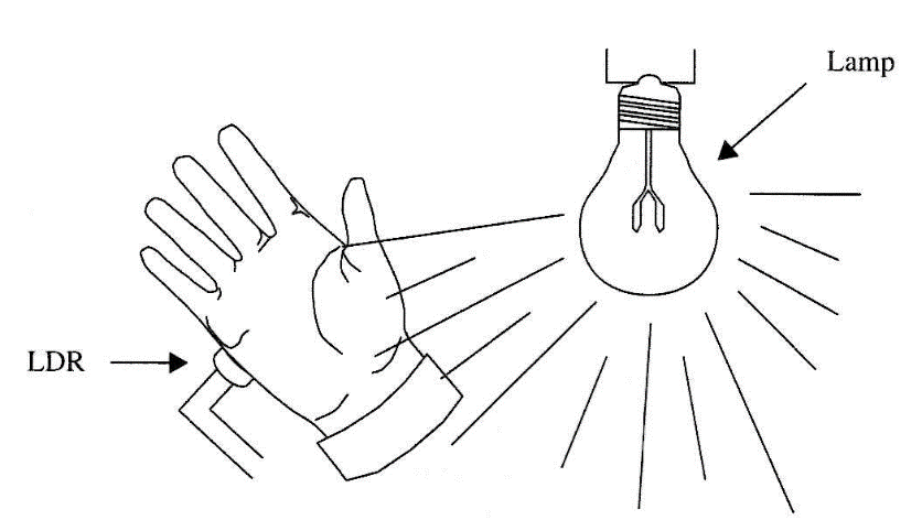
■ Place the subject's hand on the sensor and use a light source to illuminate it as shown in Fig. 3. The hand isn't totally opaque, so some light can pass through it. The circuit can be adjusted to produce a tone from this light. Alterations in this tone indicate some modification in the blood flow in the hand, affecting its opacity. Experiments with trance conditions and transcendental meditation, or during ESP sessions, can incorporate the detection of this physiological parameter using this circuit.

■ Place transparent and semi-transparent solid objects on the sensor and see if, using your mental power, you can alter the amount of light passing through them. This way, you can perform experiments involving PK.
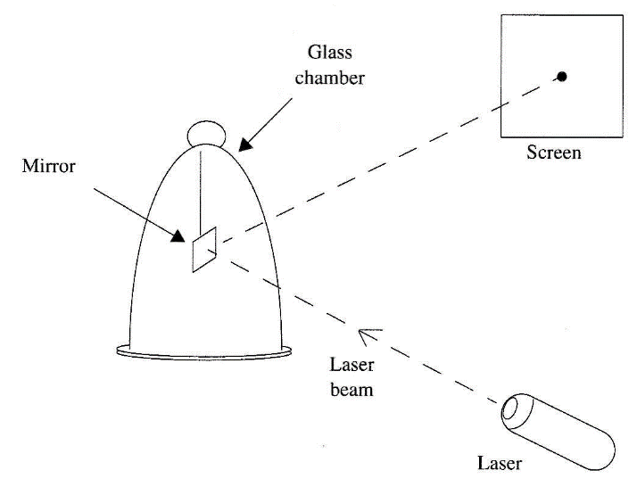
■ A mirror at the end of a nylon wire and placed inside a transparent glass chamber can be used to detect paranormal skills as shown in Fig. 4. The person who is the subject of a PK experiment must move the mirror using his mind. A laser beam focused on the mirror and reflected to a screen forms a very sensitive movement detector. Very small changes in the position of the mirror will produce a large displacement in the laser beam focused on the screen.


