Warning! High voltages are dangerous. Take extreme care when working with this device. Previous experience with this kind of device is required.
The reader can use this circuit in experiments involving Kirlian photography (electrophotography) and in other paranormal experiments such as those involving plasma or ionization. The output power of the circuit is up to 20 W, and common components are used.
Some characteristics of the circuit are as follows:
■ Power supply voltage: 117 or 220/240 Vac (ac power line)
■ Output voltage: up to 40 kV (depending on the high-voltage transformer)
■ Output power: 5 to 25 W (depending on the components used)
■ Number of transistors: 1
■ Operating frequency: 2 to 15 kHz
How It Works
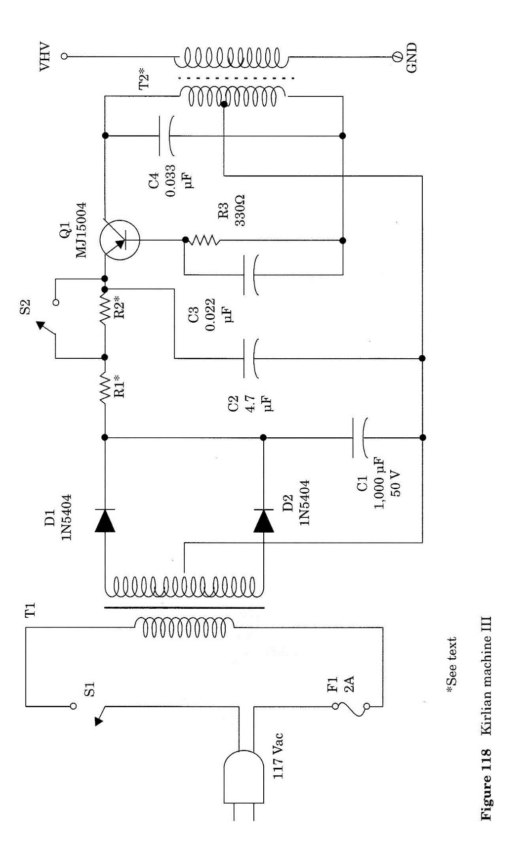
The circuit is formed by a one-transistor Hartley oscillator with the operating frequency determined by C3, C4, and the inductance of the primary side of the high-voltage transformer.
A high-power NPN silicon transistor is used in the project. This transistor must be mounted on a large heatsink due the high current drained from the supply.
R1 and R2 fix the output power by controlling the current drain of the transistor. R3 is the base bias. Depending on the characteristics of the transistor, which will vary even between units of the same type, resistor R3 must be experimentally specified in the range between 270 and 470 Ω.
The high-voltage transformer, which also determines the operating frequency, is a TV horizontal output transformer with ferrite core. The primary is formed by 20 to 40 turns of common plastic-covered wire. In the secondary of this trans-former, there appears a very high voltage that will be used in the experiments.
The power supply is simple, as regulated voltage is not needed. A 25 + 25 V transformer is recommended, but the voltage is not critical. Types with secondary windings rated to voltages between 20 and 25 V and currents between 3 and 5 A can be used experimentally.
Assembly
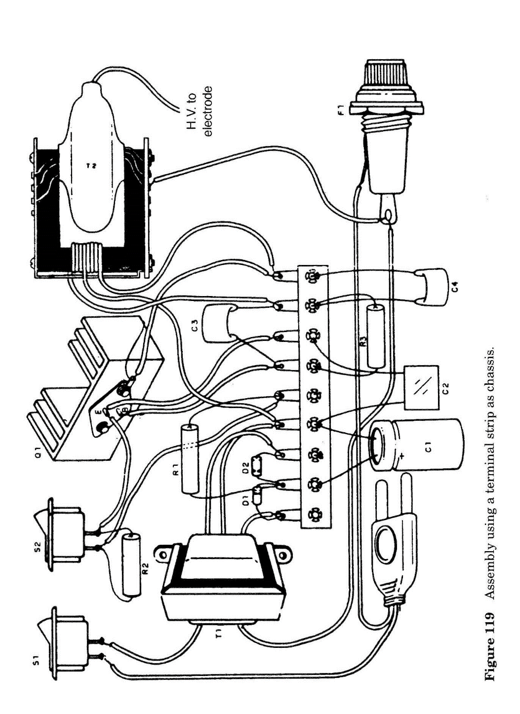
The schematic diagram of the Kirlian machine III is shown in Fig. 1. As the circuit is not critical, an alternative mounting technique is suggested in Fig. 2. A terminal strip is used as the chassis. This terminal strip holds the small components, such as the resistors and capacitors, which are connected to the other components by wires. Heavy components such as the transformer are affixed by screws directly to the box.
The terminal strip and the other components can be housed in a plastic or wooden box. As recommended in the other high-voltage projects, to avoid problems of shorts or shocks, do not use a metal box.
The high-voltage transformer can be cannibalized from any old non-functioning black-and-white or color TV. If possible, find a 21 inch or larger TV, as the high-voltage transformer used in these units can supply higher voltages.
R1 and R2 are wired-wound resistors. C1 is not critical, and values between 1,500 and 4,700 µF can be used.
The primary winding is made with common plastic-covered 22 or 24 wire (rigid or flexible) as shown in the figures, with 35 + 35 turns wound in the core. Make sure the wire is wound in the same direction after the tap.
The transistor must be mounted on a large heatsink. Keep all the wires short to avoid oscillations and other problems.
Experimenting
Plug the power cord into the ac power line. Turn on S1, keeping S2 open. The circuit will produce a light tone or hiss indicating oscillation.
Warning: Do not touch any part of the circuit when testing!
Use a neon lamp as in the previous projects. Placing the neon lamp near the high-voltage transformer causes the lamp to glow. This indicates that high voltage is being produced.
You can also use a common fluorescent lamp to detect the high voltage. Take a fluorescent lamp (even one that doesn't work anymore when plugged into the ac power line) and place it near the high-voltage terminal of the high-voltage trans-former.
If the transistor overheats, it is a good idea to replace the heatsink with a larger unit. Resistors R1 and R2 operate hot; don't be concerned about that.
The electrodes are constructed as in Project 20. The glass must be thicker in this project due to the very high voltage. Perform experiments with glass or plastic electrodes at least 3 mm thick.
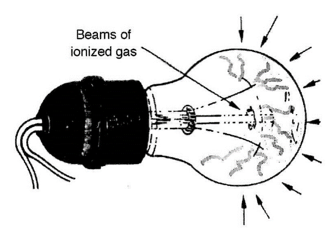
An interesting experiment is made by placing a high-power incandescent lamp at the high-voltage output as shown in Fig. 3. Common incandescent lamps are filled with an inert gas to eliminate oxygen, which would burn the filament. This is required to avoid a vacuum in the lamp, which would create an implosion in case of any impact.
Exposed to a high-voltage field, the inert gas ionizes, and you will see beams of ionized gas emanating from the filament as in a plasma lamp. The filament will not heat in this circuit, as no current flows through it. The current flows from it to the glass and from there to the air as electric charges. This is the effect you see in the common plasma lamps.
In our project, we can use any common incandescent, white, glass lamps for the ac power line (117 or 220/240 Vac) with power ratings from 150 to 500 W. Put your finger on the glass (take care!), and you'll see a flux of ions and a luminescence involving it (aura).
S2 will increase the output power of the circuit. If the circuit doesn't operate as expected, due the characteristic differences be-tween the recommended and installed components (due to tolerance variations and other factors and, in particular, if Q1 heats too much), try the following modifications:
■ Vary R3 in the range between 270 and 470 SI.
■ Vary R1 and R2, increasing them to 4.7 or even 5.6 Q.
■ Vary C4 in the range between 0.027 and 0.1 [IF
■ Vary C3 in the range between 0.015 and 0.1
■ Vary the number of turns of the primary winding of T2 from 20 + 20 to 50 + 50.
Suggestions
■ Use this circuit to power a fluorescent lamp with a high-frequency/voltage signal and make experiments picking up images or sounds (with the light-to-sound converter).
■ A wire-wound potentiometer (470 SI or 1 k SZ x 5 W) can be wired in series with R3 to control the output power, and also the frequency, of the high voltage applied to the electrodes.
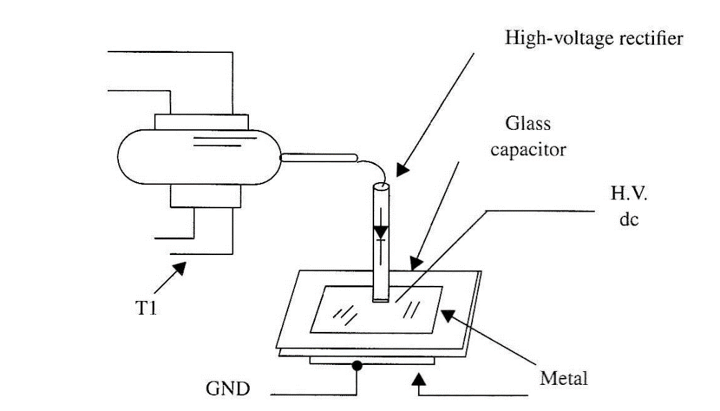
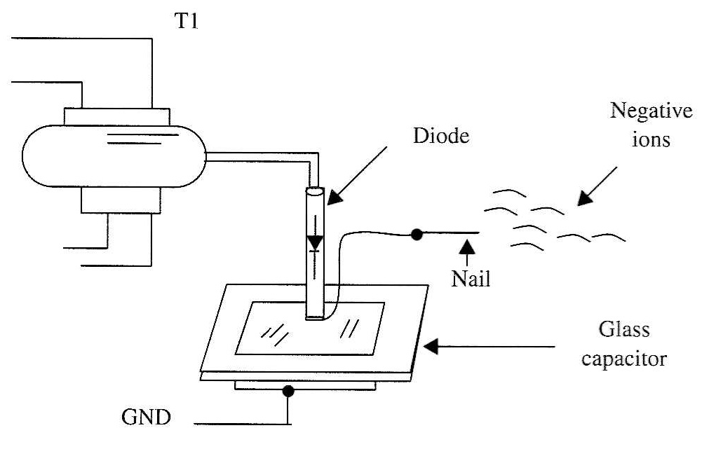
■ Figure 4 shows how a high voltage rectifier and a glass capacitor can be made to produce a high dc voltage to experiments.
■ If a nail is placed in the output voltage terminal with the glass capacitor and the high-voltage rectifier, as shown by Fig. 5, the circuit can be used to produce negative (or positive) ions in the air.
Semiconductors
Q1 MJ15004 high-power NPN silicon transistor
D1, D2 1N5404 silicon rectifier diodes
Resistors
R1, R2 3, 3 Ω x 10 W, wire-wound
R3 330 Ω Dx5W
Capacitors
C1 2,200 µF/50 V, electrolytic
C2 4.7 µF/200 V, polyester or ceramic
C3 0.022 µF/200 V, polyester or ceramic
C4 0.033 µF/200 V, polyester or ceramic Miscellaneous
F1 2A fuse
S1, S2 SPST, toggle or slide switches
T1 Transformer: primary 117 Vac or 220/240 Vac, secondary 30 + 30 V x 2 A (see text)
T2 High-voltage transformer (see text)
Plastic or wooden box, fuse holder, electrodes, terminal strip, wires, solder, power cord, etc.

