From changes in skin resistance or in the resistance of a sensor attached to any living thing (e.g., a leaf), the circuit alters the flash rate of two LEDs.
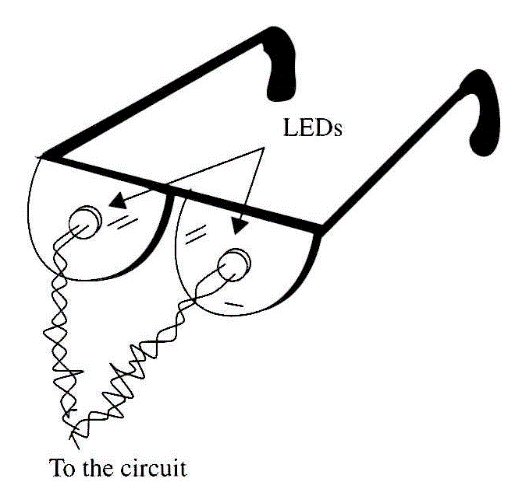
To fabricate a hypnotic biofeedback device, the LEDs can be mounted on eyeglasses as shown in Fig. 1. Many other paranormal experiments can use this circuit as suggested in the next section.
Experiments
■ The hypnotic LEDs can be used in experiments to see how the stress produced by LED flashes can alter the ESP abilities of a subject or induce him into a trance state or fourth state of consciousness. It also can be used as a monitor when the LEDs are used by the researcher and the subject acts on the sensor.

■ The flashes produced by the LEDs can be used to monitor the influence of the subject on the circuit. Changes in the flash rate must be produced by the subject using mental power only. Sensitive objects and living things can be placed between the electrodes as in other experiments described in this book.
■ Variations in the resistance of a leaf or the earth in a flowerpot can be monitored using the flash rate of the LEDs. In many experiments, the flash rate can be used as some form of feedback. For instance, you can place the plant that controls the flash rate in a lightproof box that is illuminated by the LEDs to create a circadian (i.e., 24-hour cyclical) rhythm experiment.
■ The influence of a pendulum on a living being can be monitored via the flash rate variations.
How It Works
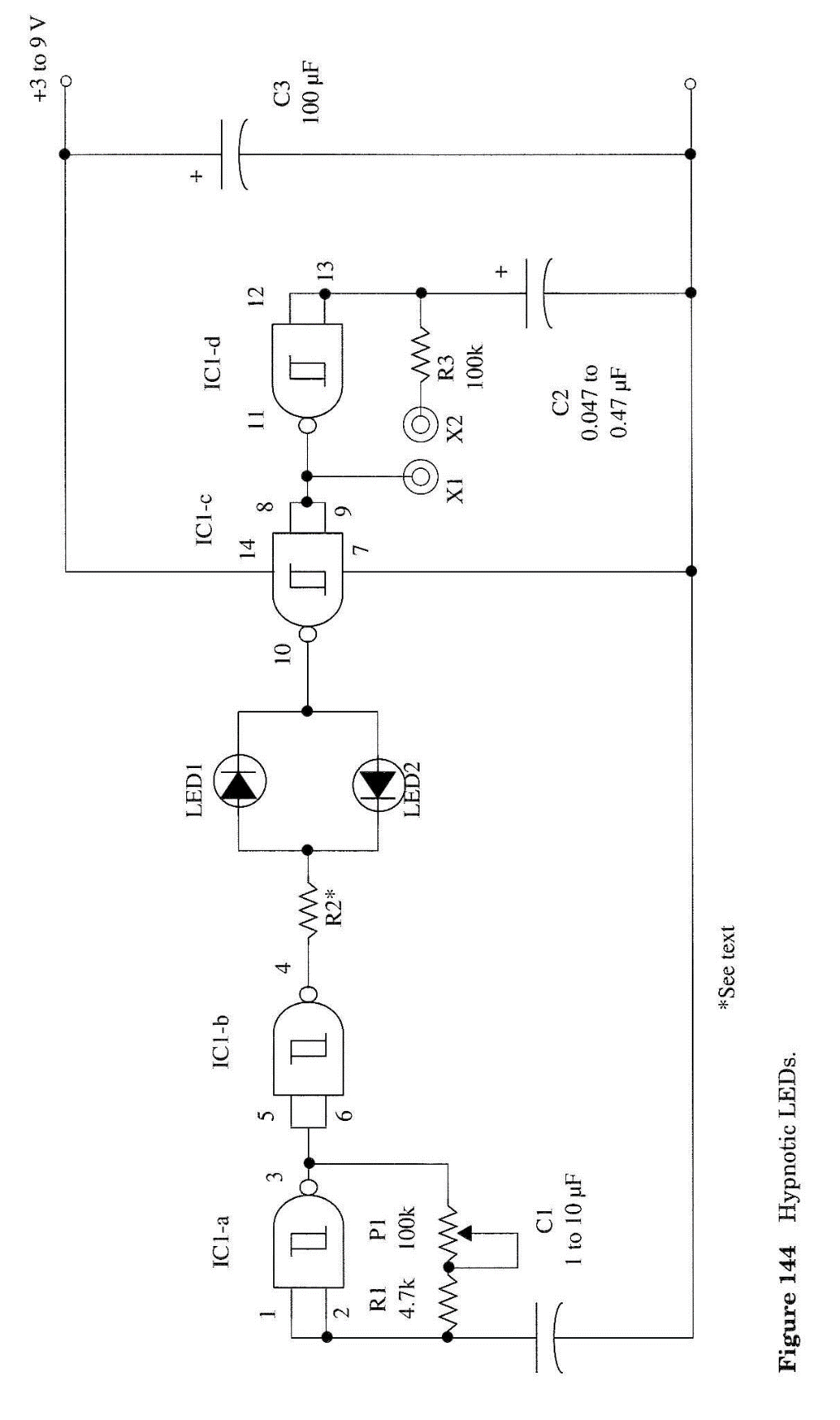
The circuit is formed by two low-frequency oscillators made with the NAND Schmitt trigger gates of a 4093 CMOS IC. The basic frequency of each circuit depends on the capacitor in the input (C1 and C2) and on the feedback network.
In the first oscillator, the feedback network is formed by R1 and C1, and its frequency can be adjusted by P1. In the second oscillator, the feedback network is the resistance between the electrodes.
The signals generated by the two oscillators are combined in two LEDs such that LED1 glows when the IC's pin 10 is high and pin 4 is low. If pin 10 is low and pin 4 is high, LED2 will glow.
As the logic levels in the outputs (pin 4 and 10) change continuously, depending on the frequency and phase of the generated signals, the LEDs will flash alternatively at a random rate.
The aim of the circuit is to control the random rate, thereby imparting to the flashes a definite pattern. This is accomplished by changing the feedback of the second oscillator, where the sensor is installed.
The fast flash rate of the LEDs can be used both to monitor and control the physiological functions of the body in a feedback application, but they have other applications. Many variations can be made to the original circuit as described in the suggestions section.
Assembly
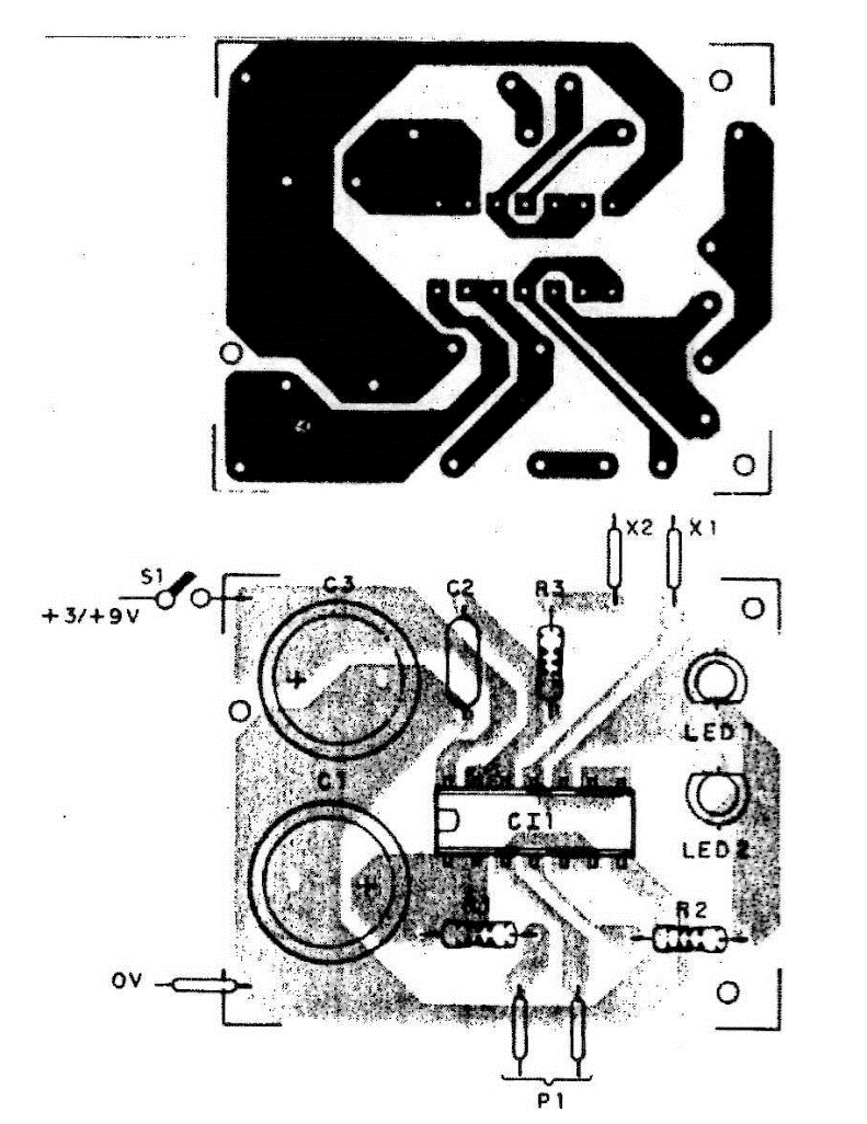
Figure 2 shows the complete schematic diagram of the hypnotic LEDs. The circuit is mounted on a small printed circuit board as shown in Fig. 2. R2 de-pends on the power supply voltage as shown in the following table.

For better results, make LED1 red and LED2 green. Capacitor C1 values can be chosen by the reader to suit the experiment. Capacitors between 1 and 10 µF can be used in this project. The value of C2 is also set experimentally to give a 50% duty cycle for the LED flashes when the subject's fingers are placed on the electrodes or when the subject is plugged into X1 and X2. Electrodes intended for biofeedback applications can be made from two metal rods.
The circuit can be housed in a small plastic or wooden box. Dimensions are basically determined by the power supply.
Using the Circuit
We can test the circuit in a basic biofeedback application by plugging two metal rods into the input as electrodes. Holding one in each hand, turn on the power sup-ply. Then adjust P1 to have a flash rate in which the on time of LED1 is approximately equal to the on time of LED2 (which varies according to applied pressure).
Now try to keep the flash rate constant. Do not alter the pressure of your hands on the electrodes—do it only by concentrating on some vital function such as your blood pressure or skin resistance. Try to control that function by willpower.
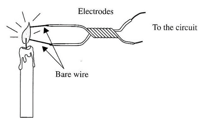
The simplest application of the device is as a feedback circuit to train people to control their physiological functions. But many other experiments can be per-formed using this circuit. One interesting configuration is a "plasma" sensor made from a candle, as shown in Fig. 4. The flame is an electric current conductor, and it forms the feedback loop that keeps the circuit in oscillation. In the case of a candle, the mystical aspect can contribute to some interesting experiments. The resistance of the candle varies constantly, altering the frequency of the oscillator. Try to fix your mind on the flame and alter the frequency of the circuit or control the flashing of the LEDs.
Suggestions
■ Alter the value of C1 and/or C2 to change the flash rate of the LEDs. Lower values can give you a stroboscopic effect (higher flash rate) that can be used in other experiments.
■ Place two other electrodes in series with PI to produce "differential biofeedback." You can control the flash rate by concentrating on both oscillators.
■ Place two electrodes in a conductive solution and monitor how the flash rate can be controlled by a subject's mind in a PK experiment.
■ Replace the LEDs with infrared types and perform experiments in ESP with "sensitive" subjects to determine if they can sense the infrared emissions.
Semiconductors
IC-1 4093 integrated circuit
LED1, LED2 Common red/green LEDs (see text) Resistors
R1 4.7 kΩ, 1/8 W, 5%—yellow, violet, red
R2 220 Ω to 1 kΩ according the power supply voltage (see text and table)
Capacitors
C1 1 to 10 µF/12 WVDC, electrolytic (see text)
C2 0.047 to 0.47 µF, metal film or ceramic (see text)
C3 100 µF/12 WVDC, electrolytic Miscellaneous
P1 100 kΩ potentiometer
X1, X2 electrodes (see text)
B1 3 to 9 V, two or four AA cells or a 9 V battery (see text)
S1 SPST, toggle or slide switch
Printed circuit board, plastic box, cell holder or battery clip, wires, solder, etc.


