One of the most important series of power transistors is formed by components whose types begin with the letters TIP. Originally launched by Texas Instruments, today they can be found, with the same type designations of several other manufacturers.
In the next lines we will give the characteristics of the main types, with reference to the characteristics of the original Texas Intruments. The same types of other manufacturers may have small differences in the characteristics. This means that in most critical projects, the assembler must be careful when using one that is not original.
Bipolar Series NPN and PNP
This series has bipolar NPN and PNP transistor ranging from the TIP29 to TIP41. In this series, the types with odd numbers are NPN types and with even numbers are PNP. The suffixes may be A, B or C according the maximum voltage between collector and emitter. Thus we have as a general rule to the transistors this series the following maximum voltages as suffix:
| Suffix | Vce or Veb (max) |
| without suffix | 40V |
| A | 60 V |
| B | 80 V |
| C | 100 V |
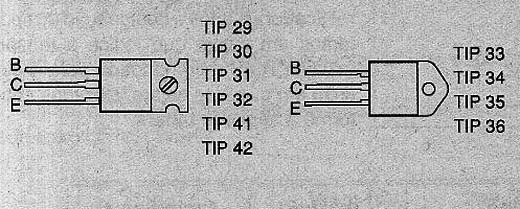
You can always use a transistor of the same type in an application, with the suffix that represents a higher voltage than the original. For example, a TIP31B replaces advantageously a TIP31A or TIP31.For these transistors have three basic types of casings are shown in Figure 1.

Note that they are endowed with resources for direct attachment to a heat sink. The following tables with the characteristics of the main types:
NPN
| Type | Vce (V) | Ic (max) (A) | hFE (min) | Pd (W) | fT (MHz) |
| TIP29 | 40 | 1 | 20 | 30 | 3 |
| TIP29A | 60 | 1 | 20 | 30 | 3 |
| TIP29B | 80 | 1 | 20 | 30 | 3 |
| TIP29C | 100 | 1 | 20 | 30 | 3 |
| TIP31 | 40 | 3 | 20 | 40 | 3 |
| TIP31A | 60 | 3 | 20 | 40 | 3 |
| TIP31B | 80 | 3 | 20 | 40 | 3 |
| TIP31C | 100 | 3 | 20 | 40 | 3 |
| TIP33 | 40 | 10 | 20 | 80 | 3 |
| TIP33A | 60 | 10 | 20 | 80 | 3 |
| TIP33B | 80 | 10 | 20 | 80 | 3 |
| TIP33C | 100 | 10 | 20 | 80 | 3 |
| TIP35 | 40 | 25 | 25 | 125 | 3 |
| TIP35A | 60 | 25 | 25 | 125 | 3 |
| TIP35B | 80 | 25 | 25 | 125 | 3 |
| TIP35C | 100 | 25 | 25 | 125 | 3 |
| TIP41 | 40 | 6 | 20 | 65 | 3 |
| TIP41A | 60 | 6 | 20 | 65 | 3 |
| TIP41B | 80 | 6 | 20 | 65 | 3 |
| TIP41C | 100 | 6 | 20 | 65 | 3 |
PNP
| Type | Vce (V) | Ic (max) (A) | hFE (min) | Pd (W) | fT (MHz) |
| TIP30 | 40 | 1 | 20 | 30 | 3 |
| TIP30A | 60 | 1 | 20 | 30 | 3 |
| TIP30B | 80 | 1 | 20 | 30 | 3 |
| TIP30C | 100 | 1 | 20 | 30 | 3 |
| TIP32 | 40 | 3 | 20 | 40 | 3 |
| TIP32A | 60 | 3 | 20 | 40 | 3 |
| TIP32B | 80 | 3 | 20 | 40 | 3 |
| TIP32C | 100 | 3 | 20 | 40 | 3 |
| TIP34 | 40 | 10 | 20 | 80 | 3 |
| TIP34A | 60 | 10 | 20 | 80 | 3 |
| TIP34B | 80 | 10 | 20 | 80 | 3 |
| TIP34C | 100 | 10 | 20 | 80 | 3 |
| TIP36 | 40 | 25 | 25 | 125 | 3 |
| TIP36A | 60 | 25 | 25 | 125 | 3 |
| TIP36B | 80 | 25 | 25 | 125 | 3 |
| TIP36C | 100 | 25 | 25 | 125 | 3 |
| TIP42 | 40 | 6 | 20 | 65 | 3 |
| TIP42A | 60 | 6 | 20 | 65 | 3 |
| TIP42B | 80 | 6 | 20 | 65 | 3 |
| TIP42C | 100 | 6 | 20 | 65 | 3 |
Meaning of the parameters:
Vce is the maximum voltage between the collector and emitter. When this specification is accompanied by "o" (open) as VCEO it means the maximum voltage between collector and emitter when the base is open.
Ic is the maximum collector current. This is the maximum continuous current that the component can support.
Static gain hFE is the current gain normally specified for a voltage between 10 V collector and emitter when the component carries a current of 1 A.
Pd is the maximum power that the component can dissipate when mounted on an ideal sink.
fT is the transition frequency, ie the frequency at which the component current gain drops to 1. In addition to this frequency component fails to amplify the signals.
Darlingtons Series NPN and PNP
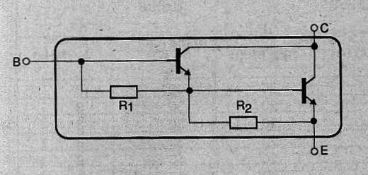
In the same way as for bipolar transistors, there is a series of TIP of Darlington transistors. In a single package then we have two transistors mounted in Darlington configuration, NPN or PNP as shown in Figure 2.

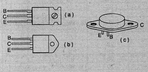
Note the existence of internal bias resistors. These transistors coording their dissipation can be found in three different casings are shown in Figure 3.

Of course, for its high dissipation, these enclosures also have resources for mounting a heat radiator. For Darlington transistors TIP series instead of suffixes, we have a sequence of numbers from the basic type indicating the maximum voltage between collector and emitter.
Thus, the NPN starts of "0" and go to "2" of the following graduation voltages:
0-60 V
1-80 V
2-100 V
For example, for TIP110 is 60 V, to 80 V is TIP111 and TIP112 is 100 V. For the PNP numbering starts at 5 and goes through 7, the following graduation voltage as the final number:
5-60 V
6-80 V
7-100 V
Thus we have the TP115 to 60 V, 80 V and to TIP116 TIP117 to 100 V, all PNP. The transition frequencies of these components are always very low, below 1 MHz, which limits their applications practically the power controls AC or DC) and circuitry of linear audio sources or amplifiers. We give in the following table with the characteristics of the main types of this series:
Darlington NPN
| Type | Vce (V) | Ic (max) (A) | hFE (min) | Pd (W) |
| TIP110 | 60 | 2 | 500 | 50 |
| TIP111 | 80 | 2 | 500 | 50 |
| TIP112 | 100 | 2 | 500 | 50 |
| TIP120 | 60 | 5 | 1000 | 65 |
| TIP121 | 80 | 5 | 1000 | 65 |
| TIP122 | 100 | 5 | 1000 | 65 |
| TIP140 | 60 | 10 | 1000 | 125 |
| TIP141 | 80 | 10 | 1000 | 125 |
| TIP142 | 100 | 10 | 1000 | 125 |
PNP
|
Type |
Vce (V) |
Ic (max) (A) |
hFE (min) |
Pd (W) |
|
TIP110 |
60 |
2 |
500 |
50 |
|
TIP111 |
80 |
2 |
500 |
50 |
|
TIP112 |
100 |
2 |
500 |
50 |
|
TIP120 |
60 |
5 |
1000 |
65 |
|
TIP121 |
80 |
5 |
1000 |
65 |
|
TIP122 |
100 |
5 |
1000 |
65 |
|
TIP140 |
60 |
10 |
1000 |
125 |
|
TIP141 |
80 |
10 |
1000 |
125 |
|
TIP142 |
100 |
10 |
1000 |
125 |
Conclusion:
In high current applications under regime of low frequencies and continuous currents these transistors, for their ease of obtaining and low cost are preferred.


