Electrolytic capacitors have not changed much in the last 50 years. Its principle of operation is still the same, and the advances which we have refer to the use of new materials and new internal architectures.
However, the basic properties are kept, the principle of operation is the same, and with this the care we must take when using them have not changed much. In other words, electrolytic capacitors are still critical components which deserve special care when used.
In fact, such care must be redoubled because modern circuits, in addition to operating with much more complex and problematic signals, are still connected to an energy network which, through the use of electronic power equipment with switched-mode power supplies, is increasingly polluted .
So that we can better understand the capacitors we will start from their electric model shown in Figure 1.

This ESL model is the "Equivalent Series Inductance".
ESR is the Equivalent Series Resistance. R is the leakage resistance and C is the capacitance of the component itself.
However, what is more problematic when we consider this equivalent circuit is that the quantities involved are not fixed.
Thus the equivalent resistance, as well as the other parasitic quantities, vary so much with the applied voltage, the frequency and the temperature of the component.
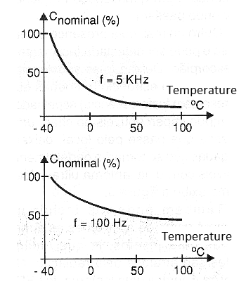
For the reader to have an idea, in Figure 2, we show how the capacitance of a common electrolytic capacitor varies with temperature.
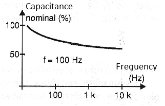
In Figure 3, we have the variation of the capacitance with the frequency of the current with which it works.
In addition, the presence of an inductance and a capacitance in series in the equivalent circuit, causes the component to have a resonance frequency which is shown in the graph of Figure 4.
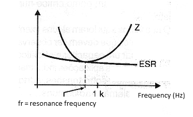
For common capacitors this frequency is between 1.5 kHz and 150 kHz.
If the capacitor operates in a circuit where the signal frequency is greater than the resonant frequency, it will behave like an inductor.
Of course, this will cause it not to be able to decouple signals, or to give them passage, if that is the function in the circuit.
Note that this frequency range is within the operation of most switched sources.
Another critical point to consider is that the capacitors generate heat when in operation.
This means that capacitors which operate with high power signals must be built so they can get rid of the heat generated. Figure 5 shows how this can be done by using a technique similar to that employed by most power components.
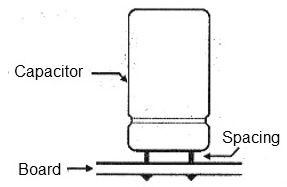
The component is kept away from the printed circuit board.
The same way, the liquid nature of the electrolyte makes the capacitors sensitive to external heat.
Never build an electrolytic capacitor too close to a component which generates too much heat.
Finally, we must still consider that an electrolytic capacitor has the specific capacitance for a given voltage. The capacitance changes with the voltage!
Connection of Series Capacitors
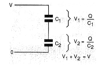
We already learned in the basic physics courses that, in the series connection of capacitors, the tensions between these components are divided according to their values, as shown in Figure 6.
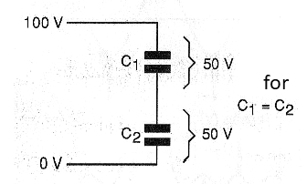
This means that two ideal capacitors of the same value, connected in series, divide the voltage of one source by two, as shown in Figure 7.
However, capacitors are not ideal and typical tolerances of up to +/- 20% can cause the voltage to be unevenly distributed between these components, as shown in Figure 8.
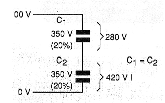
As an example, two capacitors with 20% of tolerance connected in series, we can calculate in the situation of worst case, the voltage in one of them can reach 420 V.
This will occur in the lowest capacitor within the tolerance range indicated.
One way of helping to correctly divide the voltage between two capacitors connected in series consists of the use of resistors connected as shown in Figure 9.
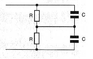
If several capacitors are connected in series-type assemblies, the voltage dividing resistors can be connected as shown in Figure 10.
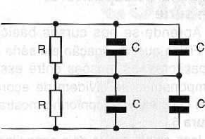
A simple formula allows us to calculate the values of the resistors which must be used in this type of application:
R = 1000 / (0.015 x C)
Where:
R is the value of the resistor in ohm
C is the capacitance in microfarad
For example, for capacitors of 4 700 uF we find the recommended resistor value for this 14 k ohm application.
It is important that the resistors used in this type of application are of excellent quality, because if they fail, problems can occur with the capacitors. Types with tolerances of 5% are recommended.
Extending the Life of a Capacitor
The power grid is full of transients and surges which can be dangerous to delicate semiconductor devices as well as to a capacitor.
The electrolytic capacitors are destroyed if they are subjected to overcurrent. To avoid that an electrolytic capacitor to be destroyed, we must consider both the surges and the transients, which are shown in the graph of Figure 11.
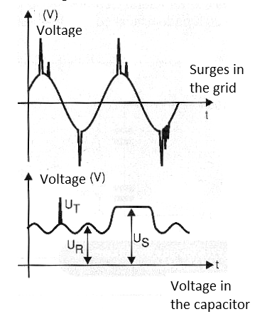
In this figure, we have Ur which is the voltage specified for the component.
Ut is the transient voltage, and for the case of the capacitors it is expressed for 1000 pulses randomly applied during the life of the component.
Us is the surge voltage, being specified for 1000 cycles for a time period of 30 seconds.
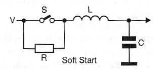
Thus, in a circuit like that of Figure 12, where we have a coil and a capacitor, the closure of the switch causes a dangerous voltage oscillation for the capacitor.
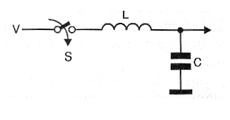
This oscillation has the waveform shown in Figure 13.
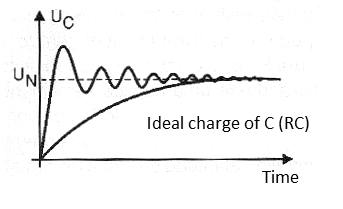
Note that for a considerable period of time the voltage in the capacitor far exceeds the nominal voltage (Un) in the capacitor and this may be enough to cause its destruction.
A solution adopted in such a circuit to avoid a problem consists of "soft start" with the use of a resistor, as shown in Figure 14.
Conclusion
Electrolytic capacitors are as sensitive components (if not more) than the semiconductor devices themselves
Its manufacturing technology is advancing, but the designer must still take great care of these components in the sense that they do not cause their destruction or make it a critical point in a design.
What we have seen are some examples of the points which must be observed when using an electrolytic capacitor, especially in industrial applications where transients, overcurrent, surges and other problems are common.


