There is also the additional problem which most of the current circuits are digital and if we want an analog waveform we need to think of an "independent" solution which involves taking up more space on a board, spending more components and eventually even having to derive a voltage different for its power.
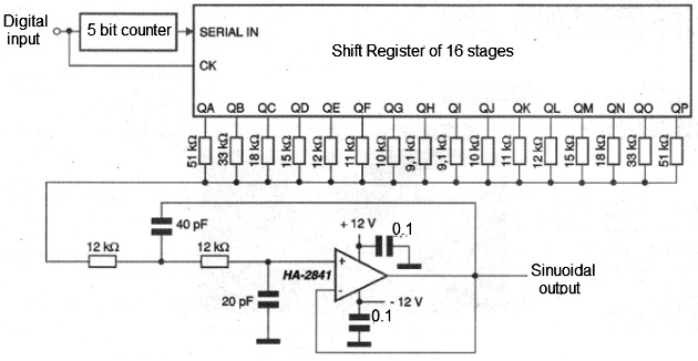
A practical idea by Intersil Corporation in its application note AN9780 (www.intersil.com) is shown in Figure 1.

What is done in this circuit is to derive a sinusoidal signal with excellent characteristics directly from a digital signal which can be obtained in the circuit in which it is to be used.
The output frequency is 1/32 of the input frequency for the 5-bit counter used, but the basic idea can be used with longer (or shorter) counters.
The use of a longer counter makes it possible to obtain a less distorted waveform.
With a greater separation between the input frequency and the output frequency it is also possible to implement the filter circuit more easily.
In this practical idea, the output of the serial counter is connected to the shift register input which then determines whether ones or zeros are shifted in the register.
Since this is a 5-bit counter, we have 16 ones to be offset, followed by 16 zeros.
The 16 ones then form the rising part of the sinusoidal waveform, whereas the 16 zeros will determine the descending part of the sine waveform obtained.
Assuming all shift register outputs are initially low, the parallel combination of resistors acts as a termination for low levels workingas ground.
The first output of the shift register Qa has a resistor of 51k, which means that when it goes to high level, it raises the output voltage slightly.
Each resistor connected to the following outputs adds a small voltage to the output signal until all of them are at the high level, when we reach the maximum value.
When the outputs start to go low in sequence, the total voltage goes down until it returns to the minimum value, forming the descending part of the signal.
The resistors were calculated to obtain a waveform as close as possible to the sinusoidal.
The output filter is a second order low pass filter with a cutoff frequency of 100 kHz.
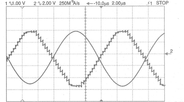
With this it is possible to obtain a fairly pure 86 kHz waveform when the input frequency is 2.78 MHz.
Figure 2 shows the waveforms obtained before and after the filter.

The integrated circuit chosen to be used as a filter was the Intersil HA-2841, which has a high pass range which is the main requirement for the preparation of an active filter.
The gain of this amplifier for this circuit should be at least 20 dB, if an equivalent is used.


