Light Source for the
Many low-cost microscopes use as their light source an ambient light focused by a small mirror or a lamp. These are often powered by one or two cells. The light from these sources is not controlled and can cause some inconvenience to the user.
A good project for the reader who has a microscope is to build a controlled light source using an electronic potentiometer as a dimmer. The complete circuit for a 6 V X 200 mA lamp is shown in figure 1.
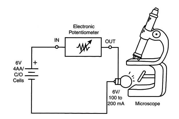
The energy source can be four AA cells or four D cells, or the circuit using a transformer can be plugged into the AC power line. This circuit can also be used to perform experiments in optics if the reader is an amateur scientist or a teacher looking for cheap resources for your lab.
Controlling a Small Heater
As a crossover into biology, your electronic potentiometer can be used to create a temperature control or ambient light control required for growing a culture or supporting the habitat of another living being.
A 22 ohm X 10-watt wire-wound resistor can be used as a heater (see Figure 2).
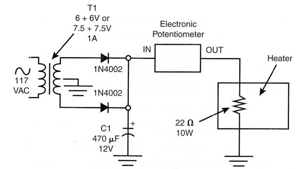
Place it in the box where the temperature must be raised, and the heat can be controlled with the potentiometer. You can replace the resistor with a lamp and perform experiments with plant growth in a controlled environment.
Simple Elevator
Figure 3 shows how to use the electronic potentiometer to control the speed of a mechatronic elevator. The switches are used to change the direction of the motors.
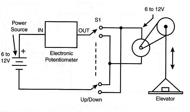
Use a gearbox or other mechanical system to reduce the speed and increase the torque of the motor.
Calculating the Dissipation
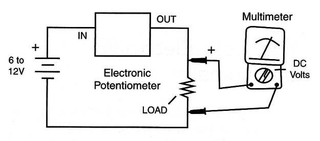
As a crossover theme into physics, the electronic potentiometer can be used to teach how Joule’s law is applied to a voltage divider. Each reader will have to calculate the amount of power dissipated by the transistor and the amount of power delivered to the load under a specified voltage.
A simple multimeter can be used to perform this scientific experiment, as shown in Figure 4.
The electronic potentiometer can also be included in experiments as crossover in the following subject areas:
Joule’s law
Voltage dividers
Association of resistors in series
Measuring the torque of a motor
The basic configuration for an electronic potentiometer can be changed and upgraded in several ways. For example, a more powerful transistor, Darlington circuits, or integrated circuits (ICs), can be used.
Other suggestions are offered in the following paragraphs.
Using a PNP Transistor
The only difference between a circuit using an NPN transistor and a circuit using a positive-negative-positive (PNP) transistor is the direction of the current flow. Figure 5 shows how you can build an electronic potentiometer using a PNP transistor.
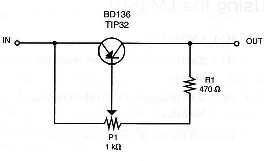
For currents up to 500 mA, you can use the BD136/138 or BD140. For currents up to 2 amps, you can use the TIP32/A/B or C. In any case, the transistor must be mounted on a heatsink.
Electronic Potentiometer Using a PNP Transistor
Q1 - BD136 medium-power NPN silicon transistor
R1 470 ohm X 1/2-watt resistor (yellow, violet, brown)
P1 - 1 k ohm - linear or logarithmic potentiometer
Heatsink for the transistor, wires, solder, printed circuit board (PCB) or terminal strip, etc.
Using a Darlington Transistor
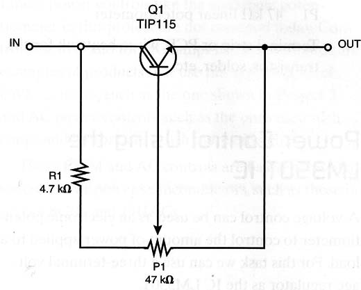
The use of a Darlington transistor allows higher values for the potentiometer. This means less heat is generated, and therefore a low-dissipation (carbon) type of potentiometer can be used.
Recommended types for this application include the TIP115/116/117, which can control currents up to 1.25 amps, and the series TIP120/ 121/ 122, which can control currents up to 3 amps. Remember to always test and practice with less current. Figure 6 shows the circuit.
Another option for incorporating a Darlington configuration is to use two transistors connected as a Darlington pair (see Figure 7).
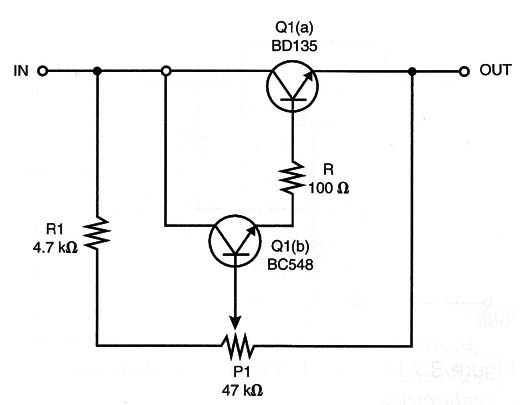
Again, when using the Darlington pair configuration, the potentiometer can be a carbon type, because the amount of current flowing across it is very low.
Using a Darlington Transistor
Q1 - TIP115 or BC548/BD135 Darlington transistor or Darlington pair (see text)
R1 - 4.7 k ohm X 1/8-watt resistor (yellow, violet, red)
P1 - 47 k9 linear potentiometer
Terminal strip or PCB, wires, heatsink for the transistor, solder, etc.
Power Control Using the LM350T
A voltage control can be used as an electronic potentiometer to control the amount of power applied to a load. For this task we can use a three-terminal voltage regulator as the IC LM350T.
This IC can source up to 3 amps to loads, applying voltages in the range between 1.2 and 32 volts. Figure 8 shows how to wire this IC in a voltage control.
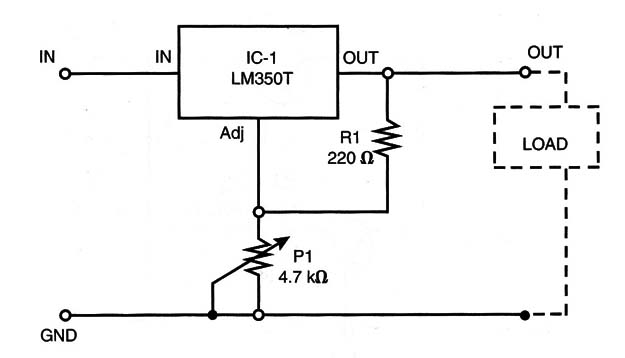
The main difference when using this circuit is that the adjust terminal must be connected to the ground.
This means that, instead of two terminals, as in the original version, this circuit has three terminals.
When using this circuit, you must plan on a drop in voltage of about 2 volts in the 1C. This means that when you require 12 volts for a load, the input voltage must be at least 14 volts.
Finally, we must observe that the minimum voltage applied to the load is not 0 volts but 1.2 volts. This is due to the internal reference of the IC, which has a zener diode of 1.25 volts.
If the application needs 0 volts as its minimum, this circuit is not suitable.
Power Control Using the LM350T
IC-1 - LM350T IC
R1 - 220 ohm X 1/2 W resistors (red, red, brown)
P1 - 4.7 k ohm - linear or logarithmic potentiometer
Heatsink for the IC, wires, solder, etc.
Constant Current Source
An important method used to control current loads is the constant current source. By using a DC motor, it possible to keep the current constant, thus compensating for changes in the load.
Therefore, with a constant current source, the power applied to the motor doesn’t have to change due to a change in the load when the motor slows down. The circuit for this application is shown in Figure 9.
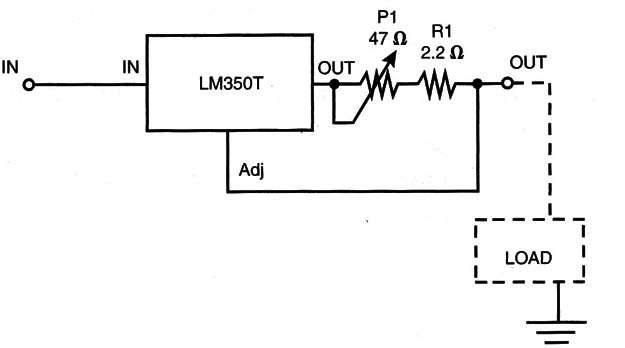
R1 is calculated according the maximum current in the load. The following formula can be used for this calculation:
R1 = 1.25/I
where I is the maximum current in the load.
It is important to observe that the minimum current in the load is not zero but is determined by the internal value of the potentiometer. For instance, when using a 47 ohm potentiometer, the minimum current will be:
I =: 1.25/47 = 0.026 A or 26 mA
In other parts of the application, this current is not enough to move the motor or to overheat it.
The input voltage Vi must be 2 volts more than the nominal voltage of the load. For instance, for a 6-volt DC motor, Vi must be 8 volts. The IC LM350T must be mounted on a heatsink, and the maximum load current is 3 amps.
Constant Current Potentiometer
R1 - 2.2 ohm X l-watt wire-wound resistor for 500 mA motors (see text for other currents)
P1 - 47 ohm - wire-wound potentiometer (see text)
Terminal strip or PCB, heatsink for the IC, wires, solder, knob for the potentiometer, etc.
The Technology Today
Linear power controls like the electronic potentiometer in this project are not common today. Controls for toys and for DC lamps in car dashboards are examples of products that use this type of control.
PWM controls, such as the ones found in this site, and AC power controls, such as the ones used with lamps and motors, are much more efficient.
These PWM and AC controls are based on oscillator circuits or power semiconductors, such as those in special SCRs and TRIACs.


