Using Transistors as Diodes
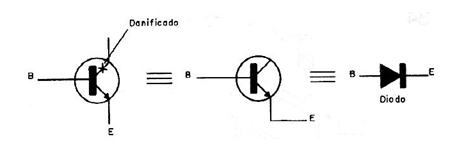
Transistors that are have good junctions can be used as diodes. Thus if we find that junction base / emitter of transistor is good using a multimeter, the component can be used as a diode, as shown in Figure 1.

The diode characteristics are the same of transistor that will be used. Thus, for transistors of the type commonly used as the BC548 the current is of the order of about 20 mA and a maximum voltage of about 20V.
For medium power transistors such as the BD135 and TIP31, the maximum current is of the order of 200 mA and a voltage of about 30V.
For a high-power transistor such as the 2N3055 the current can reach about 500 mA. Note that the current is less than the transistor collector current, since normally in the transistors the base current is much lower and it is that limit the application in this case.
Printed circuit board recovery
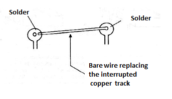
If one or more tracks on a printed circuit board are interrupted it does not mean that it is completely unusable. Track splicing can be done using a bare short piece of wire or a long piece of wire as shown in Figure 2.

Scrape the solder points off the PCB so that the solder can adhere evenly. This procedure also applies to the case where a link path is forgotten in a board design.
Impossible values for resistors
In assembly or repair work the maker may well be faced with the need to use a resistor of a value that it does not have, or that is not commercially available. If the device admits a certain tolerance we can use the nearest commercial value. For example, in a less critical mounting, instead of a 1 k ohm resistor we can perfectly experience a 1.2 k ohm or even 820 ohm resistor.
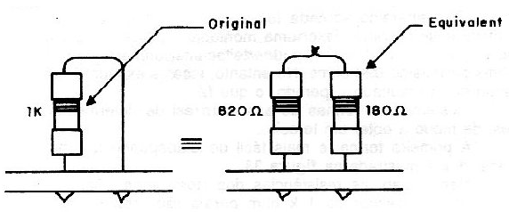
However, if these experienced values ??do not lead to the expected result, what to do? There are two ways of associating resistors of certain values ??to obtain a third. The first, and easiest to calculate, form corresponds to the serial connection, which is shown in figure 3.

In this case, the resistors resistances add up. Thus, if we do not have a 1 k ohm resistor for an application, we can connect two resistors of appropriate commercial values in series, and get a value very close to the desired value: in this case, we connect an 820 ohm resistor with one of 150 ohms or 180 ohms.
We get 970 ohms or even 1k ohms, which will probably make the device run smoothly. In this case, two resistors were associated, as shown in figure 4.

However, we can perfectly associate more resistors until we get the desired value. The only limitation for this type of solution is the space available for mounting inside the device. In Figure 5 we show how the two series resistors that replace a single "value not found" can be mounted upright on a printed circuit board.

In this type of association it must be taken into account that the higher value resistor will dissipate the highest power and therefore it must maintain the dissipation of the original type. Thus, for 1k ohms x 1W, it will be important for the 820 ohm resistor to be 1W, but the other 150 ohm or 180 ohm resistor may have less dissipation, for example 1/2W, no problem. The second way to obtain a value that cannot be achieved in a single component is by parallel association, as shown in figure 6.

A 1k ohm resistor, for example, can be obtained by connecting a 1.2k ohm resistor in parallel with one of 10,000 ohms or 12,000 ohms.
In the first case we get 1,071 ohms and in the second case we get 1,090 ohms. The formula for calculating the equivalent resistance for two resistors in parallel is:
R = (R1 x R2) / (R1 + R2)
Where:
R is the equivalent resistance
R1 and R2 are the associated resistors.
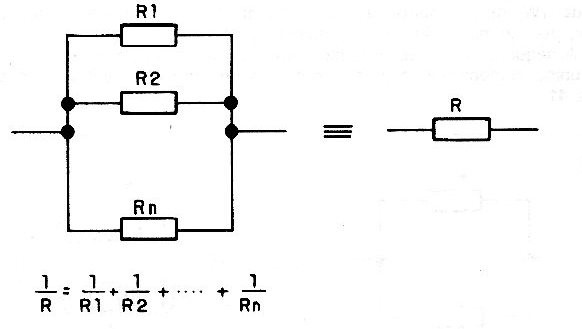
In this case, we can also associate more than two resistors in parallel, as shown in figure 7.

The formula applied to find the equivalent resistance will then be:
1 / R = 1 / R1 + 1 / R2 + 1 / R3 + ........ + 1 / Rn
Note that by connecting the resistors in series, the resistance obtained will always be greater than the largest associated resistor, and in parallel, the resistance obtained will always be smaller than the smallest associated resistor.
With practice, using a calculator, you can experiment with various combinations until you get the resistor of the value you need for a particular assembly or repair job.


