Impossible value capacitors
What we saw for resistors is also valid for capacitors. However, in the case of capacitors, we get the sum of the values when we connect them in parallel, ie "side by side" as shown in figure 1.
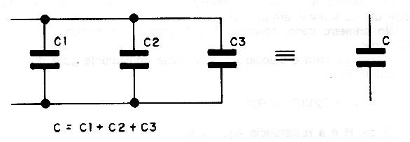
Thus, in a circuit where we notice that capacitance needs to be slightly higher than 10 nF, it is sufficient to add smaller capacitors in parallel until obtaining the desired effect, as shown in Figure 2.

This kind of improvisation is important not only when we need a capacitor of a value we do not have, but also when we need to compensate for the tolerances this type of component has. Capacitors can have tolerances as large as -20 to 50% which means that it can occur perfectly well that using a capacitor specified as 100 uF will only have 80 uF without it being bad.
Similarly, we can obtain smaller value capacitors with the serial connection. As shown in Figure 3, we can obtain a 10 uF capacitor by connecting two 22 uF capacitors in series (taking into account the commercial values and tolerances).
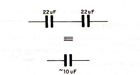
For the capacitors in series then goes the formula:
1 / C = 1 / C1 + 1 / C2 + ...... 1 / Cn
Note that it must always be noted that in parallel connection all capacitors must withstand the maximum circuit voltage. In series connection, if the capacitors are equal, they need to support only the corresponding fraction of the circuit voltage.
Small changes in the power grid voltage
Changes of some volts in the power grid voltage can be achieved by using a common power transformer as an autotransformer. In figure 4 we have an example of what we can do.
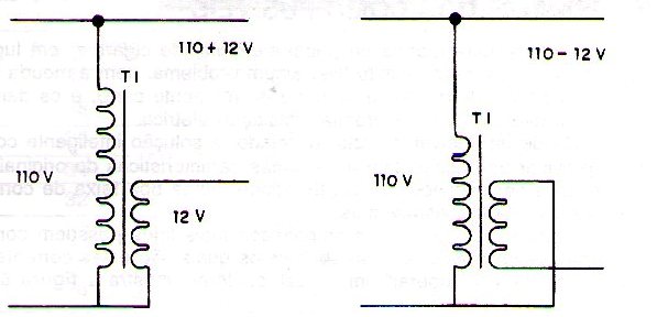
In the figure we see that, depending on how we connect the 12 V secondary winding in series with the power grid, its voltage can be added or subtracted. Thus, if the winding is in phase with the power grid, the circuit output will have a voltage that corresponds to the sum of the voltages. For example, on a 110 V grid with a 12 V transformer we get 122 Volts.
If the secondary winding is reversed from the power grid, the voltages will be subtracted. For the previous example we have 110V minus 12V or 98 Volts. Such a transformer can be used as a fixed surge protector in a location where very low voltage prevents the normal operation of an electrical or electronic device. The maximum current this type of regulator can provide depends on the transformer secondary.
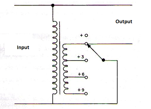
For example, if the secondary is 1 A, this means that the maximum load can be up to 1 A. In a 110V network this means 110 watts and in a 220V network it means 220 watts. With a transformer with a secondary with taps we can make a manual voltage stabilizer quite simple, as shown in figure 5.
Modifying transformers
Power transformers can also be modified to provide different voltages than originally designed. The indicated changes are those that involve small voltage reductions, as increasing the voltage without changing the entire wire requires more power and this is not always possible.
So if we have a 9V transformer we can perfectly modify it to provide 7 or 8V with some ease. This is achieved by removing the appropriate number of turns from the secondary winding of this transformer. However, for the maker the important thing is to know how many turns should be removed to obtain the desired tension and how to get access to the winding that must be changed. Fortunately, in common transformers, the secondary winding is usually done over the primary, so it is sufficient to remove the spool from the core to gain access to this winding, as shown in Figure 6.
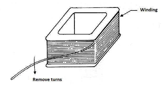
To make change then we have the following procedure:
a) Carefully remove the outer metal shield by using a screwdriver to free the core of iron blades.
b) Initially release a blade by pulling it out to release the others. Usually these blades are stuck together by a glue or resin. This substance prevents the blades from vibrating when the transformer is in operation.
c) Once released some blades will be very easy to remove the others. In this operation avoid bending or deforming the blades as they must be used again in the reassembly of the transformer.
d) Once the spool is removed, identify the secondary winding terminals. This winding for low voltage transformers is the one that uses the thickest enameled wire and is the outer one, as shown in Figure 7.
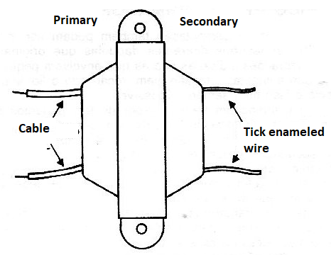
e) Remove the outer layer of paper that carefully insulates the winding, avoiding scraping the enameled wire.
f) Count how many layers of yarn correspond to the secondary winding, as this will be used as a reference to determine how many turns should be removed to obtain the desired tension. For example, if the transformer is 12 V and has 3 layers of wire, we can assume that each layer corresponds to 4 Volts. Thus, if we want to reduce the transformer voltage by 2V to get 10V we remove half of the turns of the outermost layer, as shown in figure 8.
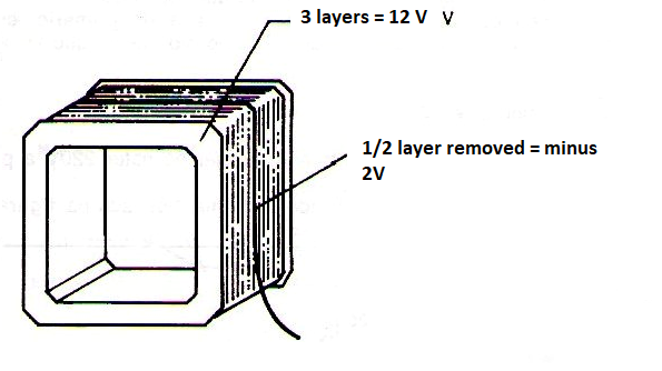
g) Once the change has been made, we pull the winding tip out again and redo the outer insulation using thick paper. We should glue this paper tightly to secure the winding and its terminal.
h) Then just reassemble the transformer by placing the core blades. To fix these plates a little melted candle can be poured to avoid vibration with the operation. However, before doing this last operation try the transformer, measuring its voltage to see if no more turns should be taken to get the desired value.
Another type of change that can be made involves completely changing the secondary winding. In this case, besides the voltage change, we can also have the current change. For example, if we have a 12V secondary winding transformer with 1A current, we can rewind its secondary to get 6V with 2A.
For that, in addition to using half of the turns, we must exchange all the wire for one that has the twice the section (cross-sectional area). Note that in this case, using a thicker wire but half the turns, the space occupied should be approximately the same, which will not make it difficult to replace the core. What we cannot do is simply swap the wire for a thicker one, but keeping the number of turns, as this will have two important implications that must be taken into account:
a) The power will be higher, and the primary as well as the core not being changed will be overloaded.
b) The larger size of the winding will make it difficult or impossible to replace the core.


