Using a common transformer as an autotransformer
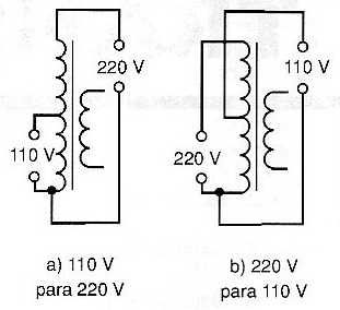
We can get 110V from 220V and 220V from 110V power grid by using the primary winding of a two-voltage transformer as shown in Figure 1. The maximum current will be given by the transformer, usually no more than a few hundred milliamperes. ie the maximum power to be connected to the output depends on the power of the transformer.
Note that there is no isolation between input and output, as one of the terminals is common. In this application it does not matter the secondary voltage or its current, as this winding will not be used.
Fire in electronic equipment
A case cited as an example in the electronics books is that of John Elton who died electrocuted while watering a fire on his television set.
Of course, everyone who works with electricity knows that water and electricity do not get along well since tap water, and even rain and spring water, is substantially conducive to the dissolved minerals it contains.
Any electronic device connected to the power grid, even having protective devices, can cause fires, and even in Brazil we our country we have cases of whole buildings burned for this reason.
What to do if electronic equipment is on fire?
Certainly, many professionals would not want to be thinking of a coherent answer just as a television, video monitor or other expensive equipment is on fire threatening their home or workshop.
The answer must be memorized for the correct procedures to be adopted.
These procedures are as follows:
• Immediately disconnect the appliance from the power supply if the cable is accessible. If it is burning or still short it should not be done with clean hands, but with the help of a thick cloth, towel or other resource.
• If the fire is concentrated only on the appliance, you can smother it with a blanket or towel. Water should only be used if the appliance has already been disconnected from the power supply. Remember that a large amount of water can do more damage than fire.
Instability in digital circuits (Microcontrollers and shields)
Many digital circuits (TTL, CMOS, microcontrollers, and shields) once assembled have instabilities with random drives and operation. This occurs in microcontrolled designs, timers, sensor circuits, priority switches, etc. One cause of instability may be the need for decoupling of the integrated circuit power pins. This can be done by attaching a 100 nF ceramic capacitor between the positive power pin and the negative or zero volt power pin of the IC as shown in Figure 2.
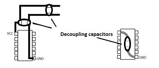
For microcontrollers and shields the decoupling can also be done with capacitors in parallel with the power supply. Electrolytic capacitors from 10 to 1000 uF should be used in these cases.
Shield issues
Why do the input wires of audio amplifiers, preamps and other circuits need to be shielded? Where does the hum that occurs when an unshielded or poorly shielded connection occurs in these cases?
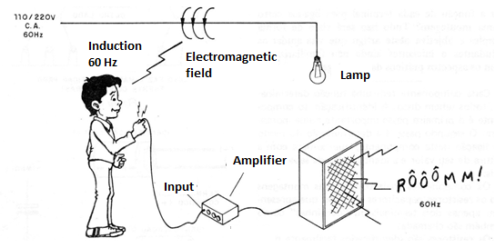
The hum we hear when we put our finger on the input of an amplifier or other audio amplification circuit has a frequency of 60 Hz that corresponds exactly to the frequency of the mains voltage. And it is precisely the power supply that is responsible for the presence of this signal practically everywhere and eventually for its entry into circuits that have not been shielded against it.
What happens is that the circulation of an alternating current through an electrical network, such as the home, creates around each conductor an electromagnetic field that induces, in any conducting body placed nearby, currents of similar frequencies.
These currents are amplified by the audio circuits and appear as sounds (snoring) in the speakers and headphones. (Figure 3)
In order to prevent this signal, wherever there is an alternating voltage network, from entering the amplifiers, their most critical points must be shielded. For this, various devices are used.
The first is shown in figure 4 and is better known. It consists of using shielded wires for all signal inputs where hum induction may appear.
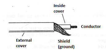
The shield must be grounded to the device so that the induced currents have a path and are thus diverted from the input circuit.
The second is shown in figure 5 and consists of the use of a common grounding point for an entire apparatus.
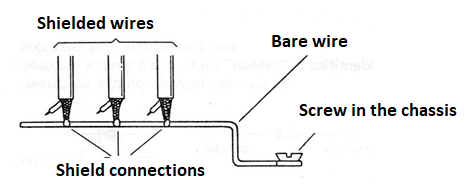
A thick wire attached to the chassis, if made of metal, is used as a low-resistance busbar, deflecting all network-induced signals that may cause snoring on the output.
Finally, we have the decoupling of the source itself, shown in Figure 6, with the use of capacitors, since transformers, being "inductive" components, can prevent induced, diverted signals from reaching ground.
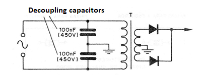
Capacitors used must be high-voltage ceramic or polyester types.
How to get thin nichrome wire
Do not throw away your open wire resistors, as there is precious nichrome wire inside of it that can be used. Just carefully break the component and have access to the wire that can then be removed and used in other projects. Resistance measurement per meter can be done with a multimeter, in which case the reader can find the right size to obtain resistance for an application.
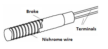
What happens is that when the resistor burns the wire it breaks but the remaining pieces can still be used.


