Printed Circuit Board cleaning
A simple method of cleaning a circuit board that is very old or has been exposed to adverse conditions and is therefore covered with rust is shown in figure 1.
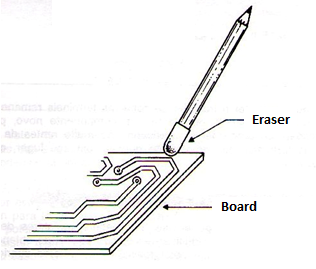
A pencil eraser is used to remove dirt and oxide. These rubbers have an ideal amount of abrasive for this application. The use of steel wool is not recommended, as the lint that may fall is conductive, thus causing short circuits dangerous to the device. Also, corrosive substances that may attack the components should not be used. Once the plate is clean the weld adhesion will be much easier and thus any repair or assembly work.
Terminal interruptions
In the most severe cases of battery leakage or even seawater attack (if the device falls into saltwater) component terminals may be interrupted with normal operation stopped. In Figure 2 we have an example of the interruption of the resistor and transistor terminals by corrosion caused by the indicated conditions.
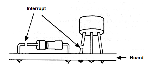
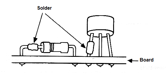
The procedure in this case is to scrape very carefully (after cleaning the place with alcohol swab) to make the shiny metal visible. Then, very carefully and quickly so that heat does not affect the component, try to make the connection between the separate terminals as shown in figure 3.
If by this procedure the appliance does not return to normal operation, the corrosive substance may have entered the component itself and caused an internal interruption. In this case, the solution is in component exchange and recovery is not possible.
This can occur, for example, in the case of capacitors where the shells are not fully sealed and corrosion can separate the terminal from the armatures internally, or in a transformer or coil. In the case of transformers and coils we will explain how to proceed to try an internal recovery.
Quick component removal
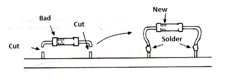
If we are sure that a component is damaged, such as a burnt resistor, we can accelerate its removal by cutting it in half with pliers, as shown in Figure 4.
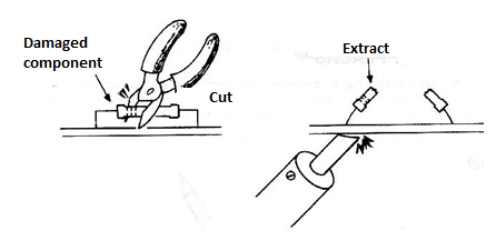
If we don't want to take the trouble of loosening the remaining terminals to save time or try a new component, we can cut the damaged component terminals not too close to the board and solder the terminals of the component in place, as shown in the figure 5.
Coil or inductor changes
Coils may also have their characteristics changed if necessary. The most interesting case is where the coils are part of resonant circuits like the one shown in figure 6.
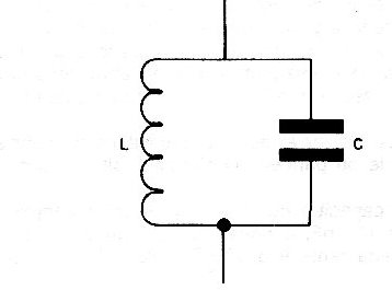
In this circuit the coil together with the capacitor determines the operating frequency or resonance. It may occur in some cases that the coil does not reach the desired operating frequency for the circuit. In a VHF receiver or transmitter, as the components have a good tolerance, after winding the coil we find that the tuning range is not desired, or the circuit does not "reach" to the desired frequency. Changes can be made in several ways:
a) Approaching or retracting the turns, as shown in figure 7 we have a first way to change the characteristics of the resonant circuit.
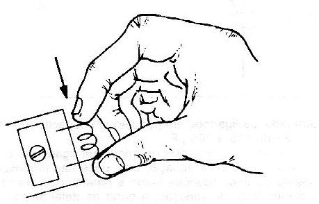
When we join the turns the resonant frequency of the circuit decreases. As we move away from the turns, the circuit frequency increases.
b) Changing the number of turns also has the same effect, but we can have it more sharply. Thus, decreasing the number of turns of the circuit increases its operating frequency. Winding new coil with more turns, we have a decrease in frequency.
c) Core: When the core penetrates a coil, as shown in figure 8, its frequency decreases.
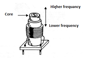
A coreless coil (air core), when receiving a ferrite core, has its action in the circuit such that the operating frequency decreases.
d) Change in diameter: This is not a very common way to change the frequency, but it can be used. When we increase the diameter of a coil, the frequency of the circuit it is in decreases because its inductance also increases.


