Using the freezer
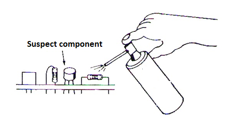
Freezer sprays are useful for discovering intermittent defects, precisely those that only occur when the appliance has been on for a while and are usually caused by heating of any component that has internal problems, such as transistors, diodes, integrated circuits, etc.
By spraying a little freeze on the suspect component when the defect is present, we can easily determine if it is the cause of the problem, as per the stages or suspect stage to know which components are suspected of an intermittent defect. (figure 1)
Repairing integrated circuit pins
Extraction work for testing or verification can damage one or more pins of an integrated circuit. The same can happen when we often use an integrated circuit in a protoboard.
Of course, without the missing pins you cannot resold the integrated circuit or fit it into a protoboard array. One way around this problem, thus recovering the damaged integrated circuit, is shown in figure 2.
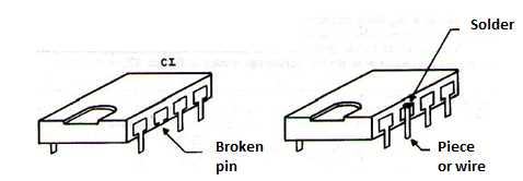
What is done is to identify which pins are missing and in their place solder small pieces of common bare wire. Then we fit the integrated circuit and do the normal welding of the terminals that are in good condition. Missing terminals will be soldered to the top of the board, with a very thin point iron on the pre-placed wires.
With the soldered pin we can also use the integrated circuit again in the experiments on the printed circuit board.
Enameled wire splices
Welding very thin enameled wires is problematic, as shaving the enamel cover to do this is very difficult. A simple way to splice very thin threads is by using a matchstick, as shown in Figure 3.
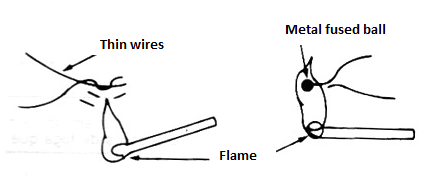
Very carefully we can use the flame to fuse the previously braided wires carefully and form a small metal pellet, which joins together such wires (solder), as shown in the same figure. The only caution we must take is that when doing this operation the enamel coating in the welded region is burned, so the wire loses insulation at this location. When reusing the spliced wire this should be anticipated by isolating this region. Nail polish can be used for this purpose.
Improvised heatsinks
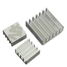
Aluminum profiles of the type used in curtain rails can be used to manufacture good efficiency heat radiators for devices that do not need large dissipations. Transistors like the BD135, TIP31 and SCRs like the TIC106 can be used with these heatsinks, as long as they do not work within their power limits.
Drill a hole to secure the component and if possible use thermal paste to ensure greater heat transfer from the component to the heatsink. Note that by screwing the component, the central terminal that contacts the fin will also be in electrical contact with the heatsink. (collector for transistors and anode for SCRs).
Heatsink mounting
Circuits that must control high powers generate heat, and this heat must be transferred to the environment. For this reason, high power dissipating components such as transistors, SCRs, Triacs, etc. must be mounted on heat sinks. The dimensions of the heatsink and the way it is assembled are of fundamental importance for heat transfer.
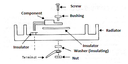
Figure 5 shows how to attach a TO-220 (plastic) enclosure component to a heat sink. Between the component and the insulator and between the insulator and the heatsink thermal paste should be placed.
In many cases, the component should not have electrical contact with the heatsink, as the tab or metal housing usually has a connection to the transistor collector or SCR anode. The proof of contact is shown in figure 6.
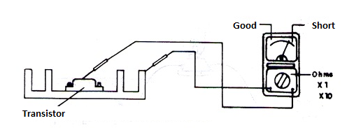
Improper contact (low resistance) may cause a short circuit.
Varnish for boards
Common varnish is a good way to protect the copper side of printed circuit boards. It prevents oxidation and the action of pollutants. However, at the time of repair, with a blade or a proper liquid remover, remove the varnish from the spot to be welded.
Likewise, remember that the varnish is insulating, preventing a probe from making contact with a track in the case of a test with an instrument.
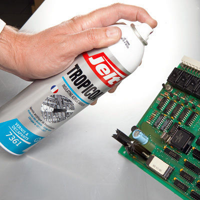
In the specialized market can be found protective spray varnishes especially suitable for electronic applications, as shown in figure 7.
