Obs. To know more about integrated circuits see article ART203E
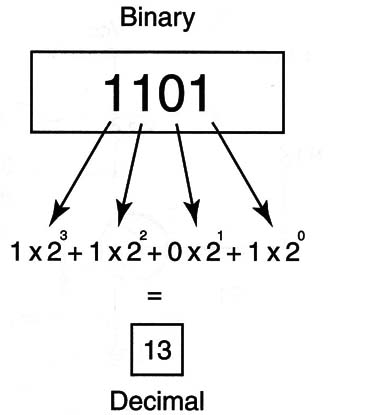
Using only two digits to represent any quantity results in a numeration system named binary. Figure 1 shows how a number in the decimal system can be converted to the binary system.

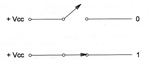
The advantage of the use of binary representation of any quantity is that it can Binary more easily be handled by electronic circuits. In the simplest form, an open switch can be used to represent a zero and a closed switch can be used to represent a 1 as shown in Figure 2.

Working with opened and closed switches it is possible to make any mathematical or logic operations with numbers.
The rules that command these operations were first established by Robert Boole two centuries ago. Moving now to the idea that a transistor (and some other components), also act as a switch, it can be used not only to represent a zero or a 1 but to execute operations with binary numbers.
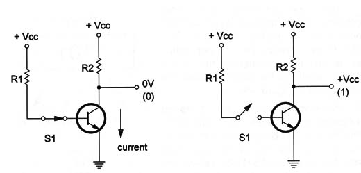
As shown in Figure 3, if a transistor is switched to a saturated state (conducting) the voltage in its collector falls to zero or a value near zero, allowing it to represent a low logic level or zero.

On the other hand, if the transistor is switched off (out), the voltage in its collector rises to a value near the power supply value. This voltage can be used to represent a high logic level or a 1.
Using many parallel transistors any complete number can be represented, and commanding them with appropriate signals, we can execute mathematics or logic operations.
A single digit, 1 or 0, that is used to represent a binary number, is called a bit and a group of eight bits is called a byte. A group of four bits is also called a nibble. A byte can be used to represent any quantity or decimal number between 0 (0000 0000) and 255 (1111 1111).
Thousands, and even millions, of transistors wired as switches can be placed in a chip in configurations that can perform any operation with binary numbers processing the bits to perform final bytes. They are digital circuits like the ones found in computers, microprocessors, microcontrollers, etc.
A certain number of basic functions are used in the projects of digital circuits.
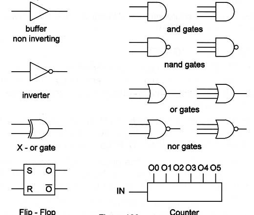
These functions are represented in Figure 4.

In the first group of basic functions are the gates. Gates are circuits that combine two or more logic levels or digital signals given as a result of logic level or signals determined by rules. The rules follow the mathematics created by Boole. In the second group are more complex functions such as flip-flops (that can store a bit), multiplexers, counters, and decoders.
The readers who want to know how a computer and digital circuits work must study digital electronics and Boolean algebra.
In the first computers, like the ENIAC (1942), operations with the bits were done by circuits using tubes. Some time later, the tubes were replaced by transistors. The next step was the use of a large quantity of integrated circuits, each containing many transistors, placed in boards.
Now almost all the circuits are inside a chip (one integrated circuit) forming processing units called microprocessors.
Although all the digital circuits are now inside the chip of a microcomputer or other advanced digital circuit, there are applications where integrated circuits performing simple operations or functions must be used.
These circuits form families of digital integrated circuits were they all have matched characteristics allowing for interconnection directly to form more complex devices.
Today, a lot of equipment uses integrated circuits of two main families, the TTL and the CMOS. See more in this site about these families.


