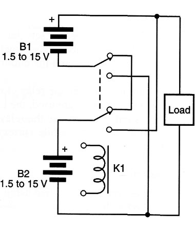
This is the same application described in MEC051 but with the switch replaced by a relay. The block shown in Figure 1 functions as follows:

When the relay is off (no current Howing through the coil), the batteries are wired in series. When the relay is energized, the batteries become wired in parallel. The batteries can be replaced by other circuits (a signal source, for instance).
Observe that the voltage applied to the relay for the control of the loads can be different from the voltage of the batteries.
Series-Parallel Switching (II)
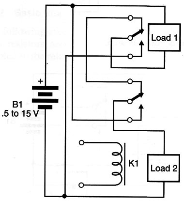
The circuit shown by Figure 2 switches two loads, connecting them in series or parallel to a power supply. When the relay is on, the loads are connected to the voltage source in series.

When the relay is off, the loads are connected in parallel. The circuit can be used to boost dc motors in robotics and mechatronics devices.
The same circuit can be used in the inverse mode switch int the loads in parallel when the relay is on.


