When an SCR or triac is used in a circuit for power control, the high-speed current changes in the load generate a series of harmonically related radio-frequency signals. The magnitude of the fundamental signal is proportional to the magnitude of the controlled current, and, in many cases, it can be great enough to cause interference in AM radios and many other circuits that use low- and medium-frequency radio signals in their operation.
ln particular, the interference level is higher when the SCR or triac controls inductive loads as motors, solenoids, electromagnets, and so on. The snap action of the triac or SCR causes current oscillations in the circuit, generating a strong electromagnetic field.
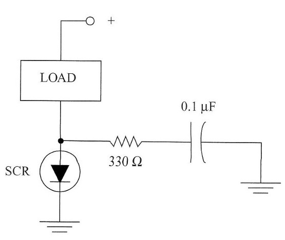
A protective circuit that minimizes interference is shown in Fig. 1. The capacitor and the resistor form a “damping” circuit that reduces current oscillation and electromagnetic interference. Examples of the EMI process include the noise in an AM radio receiver and the static displayed on a TV screen when a circuit using triacs or SCRs is turned on.

lnterference can enter radio receivers, TVs, and other sensitive devices in two ways:
1. It can be picked up from radio frequency emissions in the atmosphere (radi-
ated emissions). In this case, the undesirable signal is generally very weak and
causes problems only if a radio or other sensitive piece of equipment is placed
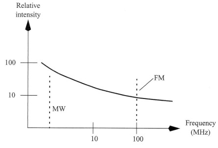
near the interference source. It is also concentrated in the low band of the radio
spectrum, as shown in Fig. 2; the interfering signal is more powerful in the
low-frequency (LF) band than in the medium-wave (MW) band.

Radio receivers operating at higher frequencies, such as FM receivers and
VHF receivers (e.g., remote controls for garage doors and robots, and cellular telephones), aren’t affected much by this interference. This is due to the
lower power concentrated in this band as well as their basic operating principles.
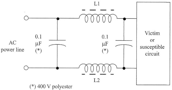
2. In the second case, the signal is conducted into the Victim equipment Via its
own AC power line. To avoid this type of interference, it is suflicient to use an
L-C filter such as shown in Fig. 3.


