The purpose of this article is to introduce the reader to the use of shape memory alloys (SMAs), solenoids, and servomotors (often just called servos) in mechatronics and robotics projects. The basic idea is to show how these devices can be used as alternative solutions for the generation of force and movement. The reader will also see how many blocks shown in the previous chapters can be used to drive these devices and how to design their circuits for practical purposes.
Theory
Mechanical power sources in practical robotics and mechatronics projects are not limited to dc and ac motors. In many cases, the desired movement or mechanical force can be advantageously provided by other categories of devices. In this chapter, we will study three of these devices in particular: SMAs, solenoids, and servomotors. The use of any of these devices depends on many factors that must be considered for each project. Knowing how they work and what they can do, the reader will be able to make the correct choice and design the elements of the drive circuit.
Shape Memory Alloys (SMA)
Shape memory alloys are materials that have the ability to return to a predetermined shape when heated. When an SMA is cold (i.e., below a temperature called the transformation temperature), it displays a low yield strength and can be deformed quite easily into a new shape that is retained by the material. However, if the material is heated above the transformation temperature, it undergoes a change in atomic structure that causes it to return to its original shape. If the SMA encounters any resistance during this transformation, it can generate large forces. In robotics and mechatronics, an SMA wire can be used as an electronic muscle, as shown in Figure 1.
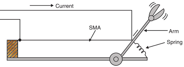
When heated by a current, the SMA length changes, and the force produced in this process can be used to move an arm, leg, lever, or other moving part of a mechanism. The most common SMA material is a nickel-titanium alloy called nitinol or flexinol. This material has good electrical and mechanical properties, long fatigue life, and high corrosion resistance.
A nitinol wire 0.02 inches in diameter can lift as much as 16 lb (8 kg). A flexinol wire only 100 microns in diameter can be deformed by 28 g of weight and produce 150 g of recovery force when exposed to a 180 mA current.
The typical SMA at room temperature is easily deformed by a small force. However, when conducting an electric current, it changes to a much harder form that returns to the original shape. A stretched SMA wire, as it shortens, produces a usable amount of force. An SMA wire can be stretched by as much as 8% of its original length.
Of course, SMAs are not recommended for all the applications. One must take into account the forces, displacements, and other conditions required for a particular application. The most important use of SMAs is in small actuators, where mechanical devices such motors and solenoids are not easy to implement.
One of the dealers of nitinol SMA is TiNi Alloy Company (http://www.tini.com), which sells some types of Nitinol wire and can provide information about its use.
Properties of Nitinol SMA
Melting temperature: 1240 –1310°C
Resistivity (high-temperature state): 82 Ω-cm
Resistivity (low-temperature state): 76 Ω-cm
Thermal conductivity: 0.1 W/cm-°C
Ultimate tensile strength: 750–950 Mpa or 110–140 ksi
Typical elongation to fracture: 15.5%
Energy conversion efficiency: 5%
Work output: 1 Joule/gram
Available transformation temperatures: –100 to + 100°C
Approximate Poisson’s ratio: 0.3
How To Use SMAs
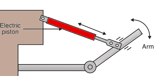
The use of SMA wires in robotics and mechatronics is simple: the wire is used to move mechanisms (arms, grippers, levers, etc.,) or employed in electric pistons.
Electric pistons, as shown in Figure 2, can be used as solenoids but act by the contraction and distension of SMAs rather than by the force of magnetic fields. The basic application is shown in Figure 3.

The length of the wire multiplied by the resistance per meter gives the total resistance of the muscle. Applying Ohm’s law, we can determine the voltage that should be used to give the amount of current required by the specific type. In the inverse manner, we can determine the length from the voltage and the current.
For instance, if we want to power a muscle using a Flexinol 250 SMA from a 12 V power supply, what is the length to be used?
V = 12 V
I = 1 A (from the specifications)
R = 12/1 = 12 Ω
The length therefore is
L = 12/20 = 0.6 m or 60 cm
The Solenoid
If you want to create a small displacement of a moving mechanical part, consider the use of a solenoid. A solenoid is formed by a coil in which a moving magnetic core can slide as shown in Figure 4.
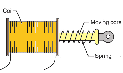
When a current passes through the coil, the magnetic field produces a force that attracts the moving core. If this moving core is coupled to any mechanism, the force that created by this process can be used to move it.
Since the force that attracts the core is present only while the current passes through the coil, and no force is produced when the current is off, a spring or other mechanism must be added to return the core to its original position. Figure 5 shows some applications of solenoids in simple mechanisms.
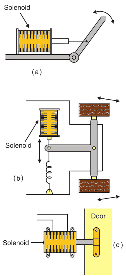
In Figure 5a, we show a simple arm using a solenoid. In 5b, we show a steering system for a robot using a solenoid. In 5c, we illustrate a system that opens a door when a solenoid is switched on.
Using a solenoid.
Simple solenoids can be wound by the designers or bought ready to be used from some dealers. The amount of force that a solenoid can provide to a mechanism depends on two factors: the current across the coil and the number of turns in the coil. Visit Mouser for informations.
The current is determined by the ohmic resistance and the voltage applied to the device. This means that the main specifications of a solenoid include the voltage and the current, and sometimes the electromotive force. In some cases, instead the current, the ohmic resistance is given. In this case, you just need to divide the voltage by the ohmic resistance to find the nominal current.
Solenoids reassemble relays in some ways: if desired, you can apply a voltage higher than the nominal voltage for few seconds to obtain short bursts of higher power. You can also apply lower voltages if you want less power.
The most common types of solenoids are designed to be driven from dc supplies in the range from 10 A down to 2 or 3 A, with voltages in the range from 1 to 48 V. But some solenoids are designed to be driven from the ac power line.
The Servomotor
Common dc and ac motors are open loop designs. Drawing current from a power supply, they perform their action by moving a shaft or a gearbox. Servomotors, in contrast, are closed loop devices. When provided with a control signal, the adjusts its action to match the signal. If the signal changes, the servomotor compensates. Servomotors are dc gear motors that include a closed loop position control. The shaft of the motor can be positioned or rotated through 180° as shown by Figure 6.
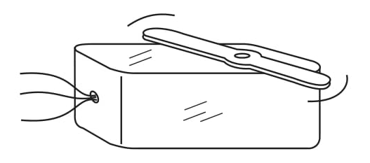
Servos are used in the hobby radio control (R/C) market for controlling model airplanes, cars, boats, and robots. The reader can find servos in many sizes according to the power required and the tasks for which they are intended. Commercial servos can be used with many of our blocks in robotic applications.
The standard servo has three wires: two for power (4 to 6 V) and ground, and the third for control. In common types, the signal is a variable-width pulse. The neutral position corresponds to a pulse of about 1.5 ms, sent at intervals of 20 ms (50 times per second). The control range (–90 to + 90°) corresponds to the pulse range of 1 to 2 ms.
If desired, you can build your own servo. Figure 7 shows a simple project. This servo is controlled by voltage instead pulses (but we can adapt it to operate with pulses). The circuit schematic is shown in Figure 8.
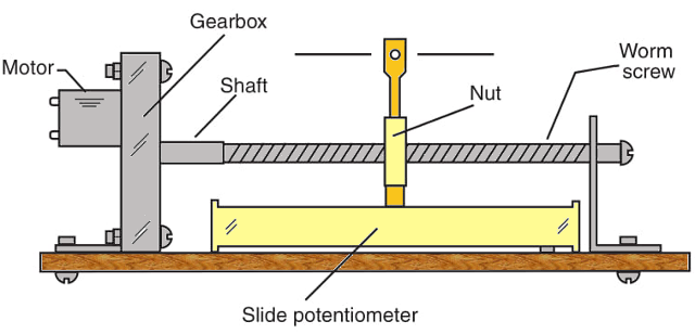
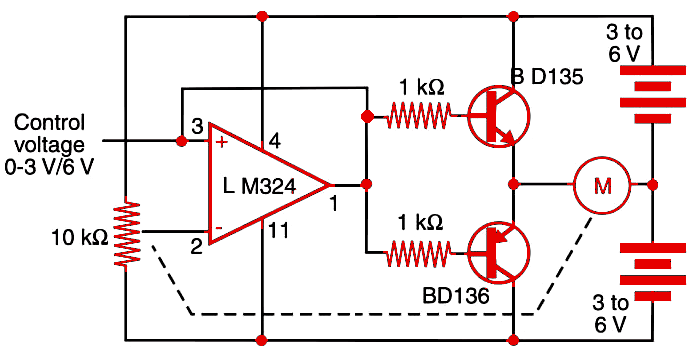
In Figure 7, a gearbox is adapted to use a worm screw that moves a nut. The nut is coupled to a slide potentiometer that gives electric feedback to the circuit. When you apply a voltage to the input of the circuit (signal), the motor moves until the potentiometer reaches a position at which the feedback voltage is equal to the input voltage (zero output). If you change the voltage in the input, the motor will be powered until the potentiometer reaches a new position where the output is again zeroed.


