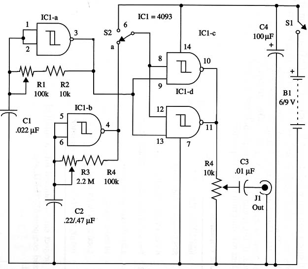
The output is adjusted from 0 to 6 or 9 V by R5, and the frequency is adjusted by R1. Modulation is adjusted by R3.
The circuit works as follows. IC1-a is wired as an audio oscillator, and the frequency is given by C1, R1, and R2. You can vary the value of C1 between 1 and 100 nF to modify the frequency range.
IC1-b is a very low-frequency oscillator that acts as a modulator. Frequency is adjusted by R3. S2 is used to select the output signal.
When S2 is in (a) we have a modulated signal at the output. When S2 is in (b) we have a continuous signal at the output. R5 adjusts the output signaPs amplitude.
A schematic diagram of the Modulated Generator is shown in Fig. 1.

The circuit can be housed into a small plastic box. Frequency calibration can be made with a frequency meter or oscilloscope.
C1 and C2 can be varied to change the frequency and modulation range. The circuit can be powered from 6 or 9 V power supplies, and current drain is only few milliamperes
IC1 4093 CMOS integrated circuit
S1 SPST toggle or slide switch
S2 SPDT toggle or slide switch
B1 6 or 9 V, four AA cells or battery
R1 100,000 ohm potentiometer
R2 10,000 ohm, 1/4 W, 5% resistor
R3 2,200,000 ohm potentiometer
R4 100,000 ohm, 1/4 W, 5% resistor
R5 10,000 ohm potentiometer
C1 0.022 µF ceramic or metal film capacitor
C2 0.22 or 0.47 µF ceramic or metal film capacitor
C3 0.01 µF ceramic or metal film capacitor
C4 100 µF, 12 WVDC electrolytic capacitor
J1 Mono enclosed jack


