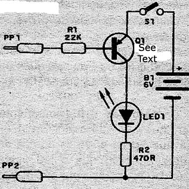
The use of a transistor in a circuit like this enables a very large reduction in the test current, which ensures the integrity of the tested components, especially if they are sensitive. Moreover, the relatively high resistance, which would not be founding a common tester with lamp or LED directly attached, may not load the device under probe due to the gain of the transistor. The tester we describe operates with four small batteries, being able to measure resistances of up to 100 k Ω.
How it works
The proof component is interposed between the collector and the base of the transistor, thus providing the bias for conduction. If the component's resistance is low enough to pass the bias current, the transistor conducts and thus the LED lights, indicating the fact.
The transistor may have gains in the range of 30 to 800, resulting in sensitivity that allows the LED to light with resistance of approximately 20 k to 1 M Ω approximately.
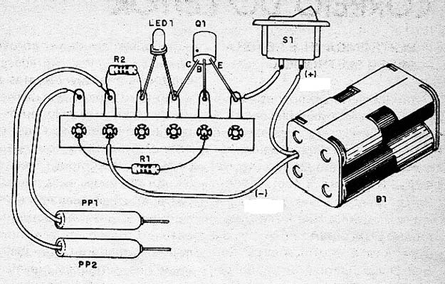
Any transistor may be used in the assembly, since the PNP type, for example, 2SB175, AC128, OC74 (old), or modern types such as BC307, BC557, BC558, etc. It is important to check its position in the assembly according to the emitter connection points (E), collector (C) and base (B). Old appliances out of use, are excellent source of transistors that can be used in this project.
Assembly
We begin to show in Figure 1 the diagram of simple components tester.


The circuit may be installed in a small plastic box and even switch S1 may be removed, and if maintaining separate PP1 and PP2 probes, no power consumption occurs. The LED should be on the outside of the box and may be any color. The probes can be improvised with large nails, if you do not want to use a commercial probe of the kind found in multimeters.
Proof and Use
Completing the assembly, put the batteries in the holder and switch S1. If the LED light is a sign that the transistor is in trouble or is reversed. It can also happen that the transistor is not the specified type (PNP). The probes should be separated.
Joining the probes, the LED should light up. If this does not occur, or the transistor is open (bad) or are the type that does not fit the project. It can also occur that is reversed.
To use the tester just touch the test leads into the terminal of the components to be tested. The component must be out of circuit or device in which it is must be off. If the LED lights for continuity and resistance is smaller than the value taken as a basis. Remember that depending on the component, so that it is good, there must be high or low resistance.
Q1 - Any PNP transistor - see text
LED - common red LED or other color
S1 - SPST switch
B1 - 6 V- 4 small batteries
R1 - 22 k Ω x 1/8 W - resistor - red, red, orange
R2 - 470 Ω x 1/8 W - resistor - yellow, violet, brown
Miscellaneous:
Terminal Bridge, probes (PP1 and PP2) of 4 small piles support yarns, welding, etc.
Note: This project, in its simplicity, is recommended for electronic courses at all levels, elementary and high school in initial activities as well as in technical courses. The assembly can also be made very easily in solderless board, universal card or a printed circuit board.


