An insulation meter is nothing more than a circuit that applies a high voltage to the component, or circuit in test, and checks for leakage current.
The current, too weak, of the order of millionths of amp, must be detected by a sensitive instrument.
The meter we propose consists of an inverter that raises the voltage of 4 common batteries to more than 400 volts, which we then use for testing.
With this voltage, a leak, even if small, results in a current which can be easily measured by a common VU-Meter.
A transformer that operates "inverted" is the basis of the design, working as a voltage elevator, in a way studied in our electronics course.
Operation
In order for a transformer to operate by alternating the voltage of a circuit, this voltage must be alternated or pulsed continuously.
As we can power the circuit with batteries (pure direct current) we must start with a change.
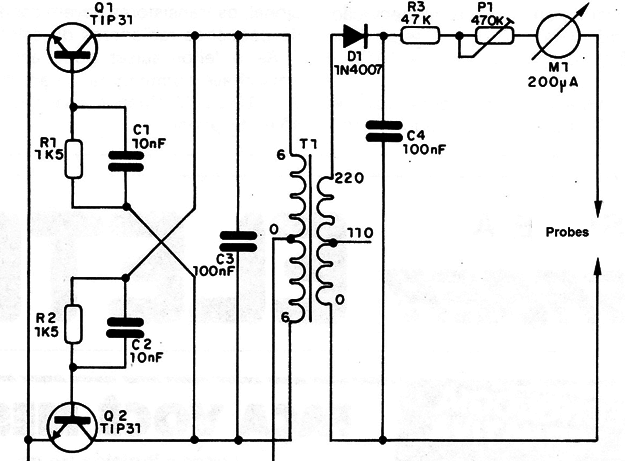
We then have an audio oscillator, in reverse, with two transistors, using the low voltage winding of the transformer to determine the frequency.
These transistors transform the direct voltage of the battery into a pulsating direct voltage that is applied to the primary (low voltage) winding of the transformer.
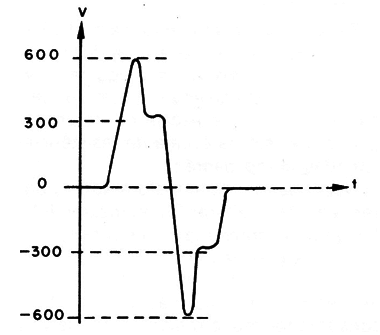
In the transformer secondary (high voltage winding) we obtain an alternating current whose peak value can exceed 600 volts in some cases.
Note that this high peak value is due to the fact that the signal is not sinusoidal, as shown in Figure 1.

The average value, if considered, will be much smaller and after rectification this is the value obtained in the probes.
In any case, if the reader touches the probes during the use of the apparatus, this with the trimpot at its minimum, the shock can occur.
The instrument is intended to indicate leakage. See that we use high voltage precisely because we have larger currents with higher resistances
Just to give an example: if we apply 1 V to a circuit having a resistance of 100 megΩ (100 000 000 Ω), the current will be only 0,01 µA, which can not be accused by a 200 µA instrument.
However, working with 500 V at the same resistance, we have a current of 5 µA that can be detected by the instrument (movement of a mark on the scale, approximately).
Assembly
In Figure 2 we have the complete circuit of the apparatus.

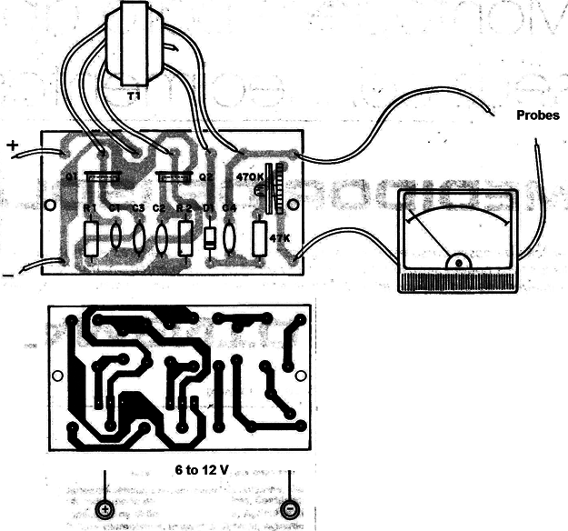
In Figure 3 we have its assembly on a printed circuit board, noting that the transformer and the batteries are installed outside this board.

Given the power consumption of the unit, it is recommended to use medium or large batteries at the source.
Having a voltmeter available with high impedance (input resistance) you can calibrate the scale according to MegΩ, using the ohm law.
Connect between the standard resistance probes (1M to 50M) and note the deflection by adjusting the trimpot to the instrument as desired.
The capacitor C4, being subjected to high voltage must have high insulation.
A type with at least 1000 volts is required for this function.
The transformer is of a power supply, with primary 110/220 V and secondary 6 + 6V, with current between 100 and 500 mA.
The instrument is a 0-200 µA microammeter of the type used in VU-meter amplifiers, however a 0-1 mA milliammeter can be used with less sensitivity to the mirror.
Test and Use
To test the device simply connect it, join the probes and check if the microammeter has its needle moved. The trimpot is then adjusted for he end-of-scale deflection or according to the scale of resistances taken as standard.
Depending on the transformer, it may be necessary to change C3 or even R1 and R2 for higher efficiency.
The running current consumption will be around 100 mA, depending on the transformer used. If the consumption is much higher (above 250 mA for example) you can increase the value of R1 and R2 to 2k2 or even 3k3.
For a 12 V power supply, which is optional, the transistors must be equipped with small heat radiators.
If the reader wants, he/she can add a switch key in the 110/220 V winding thus obtaining two test voltages.
To use it is necessary to remember that we have high voltage in the probes and that, therefore, the device under test must support it. So, do not try to test transistors, low voltage semiconductor diodes or capacitors for less than 500 V.
Q1, Q2 - TIP31 or equivalent - Power NPN transistors
D1 - 1N4007 or BY127 - silicon rectifier diode
T1 - Transformer with primary of 110/220 V and secondary of 6 + 6 V of
100 to 500 mA
M1 - VU - meter of 200 µA
P1 - 470 k Trimpot
R1, R2 - 1k5 x 1/8 W - resistors (brown, green, red)
R3 - 47k x 1/8 W - resistor (yellow, violet, orange)
C1, C2-10 nF - ceramic capacitor
C3 - 100 nF - ceramic capacitor
C4 - 100 nF x 1 000 V capacitor
Miscellaneous:
A printed circuit board, battery holder, probes etc.


