We present an interesting basic circuit in two configurations that can serve as the basis for several practical projects.
As a function generator we can use the circuit to produce programmed waveform signals in a frequency range ranging from hertz fraction up to about 200 kHz typically.
The waveforms synthesized from rectangular pulses can be applied to low-pass filters and with this we will have different standards for use in musical instrumentation or even in the test of sound equipment.
In the monostable application or as a fixed voltage generator to each input pulse the output one of the four preset voltage levels appears.
In this configuration the circuit can be used as a digital command of dimmers, motor speed or even for the adjustment of instruments or data acquisition systems.
The circuit can be powered with voltages from 5 to 12 volts, these being the typical values of the maximum output voltage of the generated signals.
The maximum operating frequency depends on the number of levels that can be generated by getting around 200 kHz for a power supply of around 10 V.
HOW IT WORKS
The input of the circuit supports two configurations. We can use a monostable 555 triggered by the negative input pulse on its pin 2.
We can trigger this circuit with touch sensors or from external digital commands.
The single output pulse generated in these conditions is brought to the input of a 4017 counter which in the basic version counts up to 4.
We then have at each instant, according to the input pulse one of the 4 outputs of the 4017 taken to the high level.
These outputs are connected to a digital switch which can either be connected to the positive of the supply or can be supplied by a different external signal, for example from a second oscillator.
In the condition where the signal comes from the power itself it goes to the corresponding output to the activation of the 4017.
At the output of the 4066, set of digital keys, we have 4 trimpots which adjust the corresponding level of the signal or voltage that will appear in the output.
In the monostable version with each touch we have the production of an output voltage according to the trimpots adjustment.
In the astable version, the 555 produces a sequential switching signal for the 4017 and the 4066 key so that the outputs set in the trimpots continuously run generating a waveform as suggested in Figure 1.
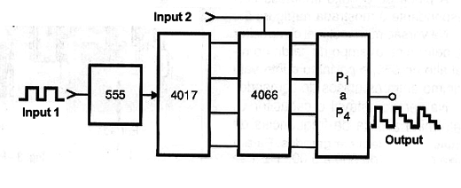
If the 4066 is fed by an external signal we will have the sequencing of this signal at sequential levels with the mixture to the signal generated, in which case the circuit can be used to generate waveforms or special effects.
The output voltage of the signal depends on the circuit power which can be made with voltages typically between 5 and 12 volts.
Since the 4066 CMOS switches have an ON resistance of the order of 150 Ω, the maximum output current in each output with 12 volts will be of the order of 8 mA.
ASSEMBLY
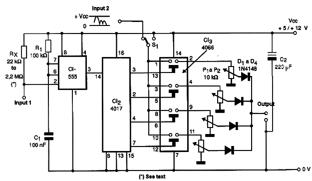
The circuit in the monostable version is shown in Figure 2.
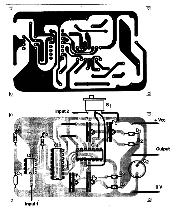
The printed circuit board for this version is shown in Figure 3.
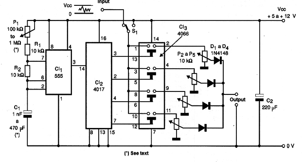
For the astable version we have the circuit shown in Figure 4.
The corresponding printed circuit board is shown in Figure 5.
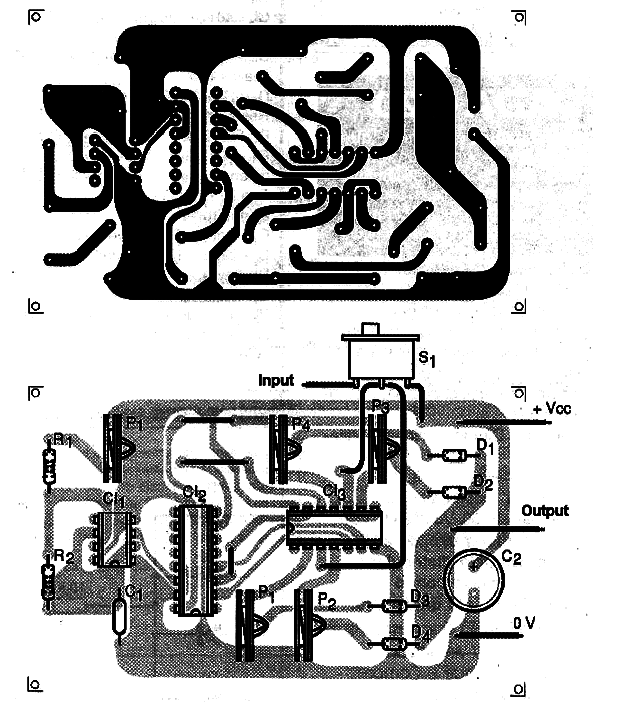
In the monostable version the C1 capacitor determines the output time at the high level of the 555 and therefore the minimum interval between the command pulses.
In the stable version the capacitor C1 determines the frequency range of signals that can be generated. For the audio range from 500 to 5 000 Hz use a capacitor of 47 nF.
For very low frequencies use an electrolyte from 4.7 to 220 µF.
Trimpots are common and the other components are not critical. The 4066 integrated circuit may be replaced by the equivalent of higher internal resistance which is the 4016 provided that such a change of feature is not important in the intended application.
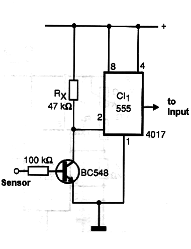
For a touch triggering we have the configuration shown in Figure 6.
ADJUSTMENT AND USE
In the monostable version the value of resistor R1 depends on the type of the signal used in the trip. Higher values ??are used with low sensitivity sensors or touch sensors.
To adjust the output voltage levels a common multimeter can be used at the appropriate range of continuous voltages.
Apply the command pulses to the input in sequence and adjust the desired voltage levels to the corresponding trimpots.
For more voltage levels the 4017 can be configured to count up to 8 and two 4066 integrated circuits with 8 output adjustment trimpots can be used.
To adjust the waveform use a low pass filter as shown in Figure 7 and connect the circuit to an oscilloscope.
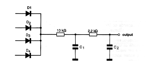
The value of the capacitor will depend on the range of frequencies to be generated.
Once the operation is verified, it is only necessary to use the device independently or coupled with some other project.
Circuit 1 - Monostable
Semiconductors:
CI-1 - 555 - integrated circuit - timer
CI-2 - 4017 - CMOS integrated circuit - Johnson counter
CI-3 - 4066 - CMOS integrated circuit - A/D keys
Resistors: (1/8W, 5%)
R1 - 22 k ohm to 2.2 M ohm - see text
R2 - 10 k ohm to 100 k ohm - depends on the application
P1, P2, P3, P4 - 10 k ohm - trimpots
Capacitors:
C1 - 10 nF to 100 nF - depends on the application
C2 - 220 µF/12 V - electrolytic
Miscellaneous:
S1 - 1 pole key x 2 positions
A printed circuit board, sockets for integrated circuits, wires, solder, etc.
Circuit 2 - Astável
Semiconductors:
CI-1 - 555 - integrated circuit - timer
CI-2 - 4017 - CMOS integrated circuit - Johnson counter
CI-3 - 4066 - integrated circuit CMOS - A/D keys
Resistors: (1/8 W, 5%)
R1, R2 - 10k Ω
P1 - 100 k Ω to 1 M Ω - trimpot or potentiometer - see text
P2 to P5 - 10 k Ω - trimpots
Capacitors:
C1 - 1 nF to 470 µF - see text
C2 - 220 µF/12 V - electrolytic
Miscellaneous:
S1 - 1 pole key x 2 positions
A printed circuit board, sockets for integrated circuits (optional), button for potentiometer, wires, welder, etc.


