Good insulation should mean a resistance of at least 5,000,000 ohm in a normal application. This is the minimum resistance we tolerate, for example, between the armatures of a capacitor, other than electrolytic (up to 1 uF) ,between two wires, conductors of a power cable, or between the poles of a switch that is open.
Of course, there are less critical applications where moisture may be present in a more constant condition and smaller insulation resistances can be tolerated.
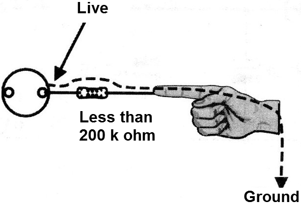
Only with resistances of less than 200,000 ohm in the 110 V and 220 V network, contact with a person can cause a shock, see Figure 1.
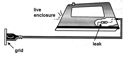
This is the case, for example, of an iron (which normally accumulates moisture, mainly vapor types) where the casing may have a slight contact with the feed, characterizing an insulation leakage, see Figure 2, If this leakage represents a lower resistance than the values ??quoted, an accidental touch on the iron may, in addition to the burn, if it is hot, cause a very dangerous shock under the conditions in which the appliance is used.
Thus, it is interesting that the appliance repairer has an insulation leak detector which gives a signal when the resistance present in this leak reaches certain values.
The circuit we describe has two detection ranges: one in which only if the insulation represents a resistance less than 200 k ohm, the warning signal occurs and another, where this will occur for resistances below about 10 M?.
The device is compact enough to fit easily in the pocket or in the service desk of the technician, and low cost, because it uses absolutely common components.
Its assembly is also very simple because the components are not critical and there are no adjustments.
HOW IT WORKS
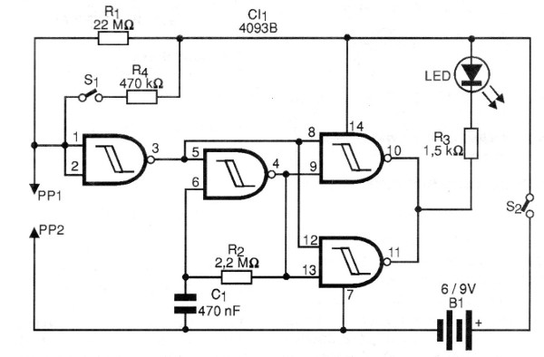
We use a sensitive 4093 type integrated circuit which has four doors that can be connected in different ways. The first port is connected as an inverter.
This port maintains its output at the low level (pin 3 with 0 V) ??when the voltage at pins 1 and 2 is at a value which is approximately 2/3 of the supply voltage. If this voltage falls below 1/3 of the supply voltage (approx.), the inverter changes state and thus the output becomes positive.
Thus, by connecting at the input a divider formed by R1 and the circuit being tested, the output of the inverter will be positive if the resistance of the tested device is less than half the resistor and will be zero if the resistance exceeds this value.
The output of the inverter controls two other circuits formed by the remaining ports of the 4093 integrated circuit. The first is a slow oscillator which remains inhibited when the inverter output is at the low level and goes into operation when it goes high.
In operation, this oscillator combines its signal to the inverter in the last two ports which form a buffer-driver that drives an LED.
Thus, if the leakage resistance of the circuit under test is high, nothing happens and the LED does not light, but if it is low, the oscillator starts and the LED flashes.
The switch S1 changes the resistor of the divider so as to obtain circuit switching with a lower resistance. In this position the circuit also operates as an excellent continuity tester.
ASSEMBLY
In Figure 3 we have the complete tester diagram.
The arrangement of the components on a printed circuit board is shown in Figure 4.
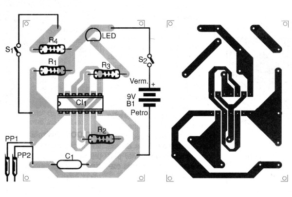
We suggest that the integrated circuit be built on a DIL socket. The LED can be any color and the resistors are 1/8 W or larger. C, is a polyester or ceramic capacitor and the probes are common red and black.
For the power supply, 4 small batteries or 9 V battery can be used, always observing their polarity in the connection.
S1 and S2 are simple switches of any type.
The unit easily fits into a small box the size of a cigarette pack or soap dish. In fact, plastic soap dispensers consist of an excellent suggestion of box for this assembly.
TEST AND USE
To test, simply touch one probe on the other, or in the most sensitive position (with S1 open), and hold the probes. The LED should flash. The frequency of the blinking depends basically on R2, which can be changed in the range of 470 k ohms to 4.7 M ohms. The capacitor C1 can also be between 100 nF and 470 nF, whereby a change in the frequency of the blinks is obtained.
To use, the tests must be done with the test device switched off.
In Figure 5 we show how to test the insulation between the casing and the power cable of an iron.
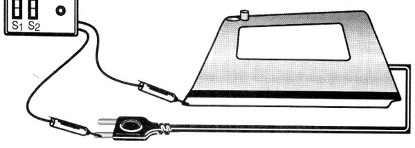
This test must be done with S1 closed, that is, in the position of lower sensitivity. This same test is used to test the insulation of transformers and other appliances.
For small capacitor testing, use the highest sensitivity (S1 open).
When you touch the capacitor with the probes, the LED may flick, meaning the charge of the capacitor, but then it should remain off.
If the LED flashes continuously thereafter, the capacitor is shorted or leaking.
For electrolytics, depending on the value, somewhat high leaks can be tolerated. Thus, for capacitors larger than 100 uF, the leak test with this device is not significant.
Semiconductors:
Cl1 - 4093B - CMOS integrated circuit
LED - common red LED
Resistors: (1/8 W, 5%)
R1 - 22 M ohm
R2 - 2.2 M ohm
R3-1.5 k ohm
R4-470 k ohm
Capacitor:
C1 - 470 nF - ceramic or polyester
Miscellaneous:
B1 - 6 or 9 V - 4 batteries or battery
S1, S2 - Single switches
PP1, PP2 - Probes
Printed circuit board, integrated circuit socket, battery holder or battery connector, assembly box, wires, welding, etc.


