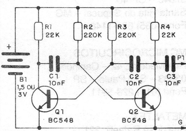
The use of an astable multivibrator, which provides a harmonic-rich rectangular signal, allows the injector to be used not only in low frequency (audio) circuits, but also in RF stages.
In fact, the harmonics of this circuit extend to frequencies high enough to allow the testing of AM and FM circuits as well.
The proposed design uses only two general-purpose transistors, oscillating around 1 kHz. Power can be supplied with either two standard batteries or with a single battery if a more compact assembly is desired.
The signal strength is quite good and can even excite the audio output stages of small amplifiers.
How it works
In an astronomical multivibrator each transistor alternately conducts the current at a frequency which is given by the formula:
f = 1 / (1.1 x R x C)
at where:
R is the base bias resistance of the transistor and C is the coupling capacitor in Farads.
The collector resistor is calculated to have a value of approximately R / 10, thus assuming a minimum gain for the transistor which provides the possibility of oscillation.
For a 220 k base resistor, we can then fix the collector resistor at 22 k, which will also be responsible for the average current consumed by the injector.
This current can then be calculated by:
I = 3 / ( 22 x 103 )
I = 0.13mA
l = 130 uA
It is therefore quite low current consumption which guarantees excellent battery life.
Assembly
In figure 1 we have the complete circuit of the injector.

In figure 2 we have the assembly on a printed circuit board which also serves as a support for the battery (s).

The capacitors are ceramic and the resistors 1/8 or ¼ W.
The signal injection tip can be made with a large sewing needle, which admits the weld.
Negative bonding is achieved by means of an alligator clip.
Test and Use
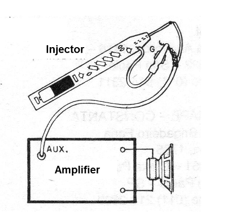
The proof is simple: simply inject the signal from the device at the input of any amplifier, as shown in figure 3.

There should be normal playback of the generated sound, ie a high intensity high-pitched whistle.
The use of the injector should be approached in another article of this series, since it admits innumerable possibilities.
We can only advance that the injector simulates the signal of a station, turntables or tape players, and should be applied to the input of each stage of the apparatus.
The sound must be reproduced in intensity depending on the position of the stage. If this does not occur we will have a disabled stage.
Q1 - Q2 - BC548 or 2N2222 - NPN transistors
R1, R4 - 22k x 1/8 W - resistors (red, red, orange)
R2, R3 - 220 k x 1/8 W - resistors (red, red, yellow)
C1, C2, C3-10 nF - ceramic capacitors
B1 -1.5 or 3 V - 1 or 2 small batteries
Miscellaneous: battery holder, printed circuit board, alligator clip, wires, solder, needle etc.


